The design procedure for the Strong Frame connection parallels the design concepts for frames with other moment connections but is adapted to the specific configuration of the connection. Connection flexural strength is controlled by the strength of the Yield-Links, and shear strength is controlled by the strength of the shear-plate connection. This allows beams to be designed, if desired, to be unbraced yet stable under the combined effects of expected ultimate connection flexural strength, gravity loads, and axial load resulting from lateral loading. Unlike some historical PR moment connections, the Strong Frame connection is proportioned to remain elastic under the combined effects of design lateral and vertical loads, with the Yield-Links only experiencing inelastic behavior during seismic events in which the real seismic forces are expected to exceed the unamplified design seismic forces (Rex and Goverdhan, 2000). This permits the use of typical elastic analysis procedures similar to other SMF connections. However, like some historical PR moment connections, the beams are designed as simple span for gravity loads (Geschwindner and Disque, 2005). This facilitates post-earthquake repairs, should they be needed, by ensuring the beam is proportioned to support its design gravity loads even if the Links are removed during replacement. In addition to the various strength checks for frame members and elements of the connection, the PR nature of the Strong Frame connection requires a detailed stiffness check using actual connection stiffness to ensure lateral drift limits are met. This means that the lateral stiffness-to-mass and lateral yield strength-to-mass ratios are required to be the same as any other frame using SMF connections. As such, the code equations for base shear and period estimation are equally applicable to frames using the Strong Frame connection as they are to frames using other SMF connections. This was verified as part of the nonlinear response history study comparing Strong Frame and RBS connections discussed previously. For each of the archetype structures, the periods of the RBS frames and Strong Frame frames were virtually identical.
The design process can be iterative, and Step 1 begins with suggestions on how to create trial values for sizes of the frame members and provides an initial estimate of story drift which is explicitly checked later in the design procedure. In addition to designing the beam as simply supported, Step 2 also suggests a deflection limit on the beam to limit member end rotations that would affect the connection.
Step 5 determines the width of the yielding portion of the Link based on the permitted thicknesses ranging from in. (13 mm) to 1 in. (25 mm) and subject to limitations that include a maximum width of 6 in. (150 mm), which corresponds to the strongest Yield-Link that has been qualified. Testing showed that for the approved steel grades, if the length of the straight portion of the yielding section of the Link is proportioned such that the strain demand in that section does not exceed 0.085 when the connection is subjected to a rotation of 0.05 rad, the Link will possess sufficient toughness to enable the connection to meet the cyclic test performance requirements of the AISCE Seismic Provisions, and this is reflected in Step 6.
In Step 7, the Link expected yield strength and probable maximum tensile strength are computed. The value of is specified as 1.2 to reflect the proper value from the 2016 AISC Seismic Provisions Table A3.1 for ASTM A572/A572M Grade 50 (Grade 345) plates, strips, and sheets. If the Link is fabricated from hot-rolled structural shapes of ASTM A992/A992M or ASTM A913/A913M Grade 50 (Grade 345) as permitted, the tabulated value of is used.
In Step 8, the Link-to-beam flange connection is designed. Both here and in the web shear-plate connection, bolt bearing is required to be designed using bearing values that limit deformation at the bolt hole. The purpose of this is to again drive the inelastic response into the reduced portion of the Link and to keep other areas of the connection outside of the link essentially damage free to facilitate Link replacement should it be desired after a seismic event.
In Step 9, the Yield-Link connection to the column flange is designed. Step 9.1 determines bolt tension demand from either T-stub Yield-Links or end-plate Yield-Links, as appropriate, for design of the bolts. While the end-plate Yield-Link is similar to the prequalified 4-bolt extended, unstiffened end plate (4E), the yield line mechanism in the end-plate Yield-Link is slightly different. Conservatively, the T-section two-yield line model reflected in Equation 12.9-10 is used to design the end-plate Yield-Link. In Equation 12.9-9, the second term is additional tensile force assigned to the two bolts directly adjacent to the single-plate shear connection due to the moment that results from the eccentric application of shear to the single-plate shear connection. Shear transfer from the end-plate Yield-Link to the column flange is accomplished through the bolts at the compression flange location of the end plate, which are checked in Step 9.1a. In Step 9.2, the required Yield-Link flange thickness, for a no prying action condition with a force limited by the probable maximum tensile strength of the Link as reflected in the calculation of in Step 9.1, is determined.
Step 10 has been expanded to include specific design provisions for checking the elements of the buckling restraint assembly, which include BRP thickness, beam flange thickness, and BRP bolts. Step 10.1 determines the required minimum thickness of the BRP. is the lever arm from the start of the reduced region of the Yield-Link to the edge of the first spacer plate bolt hole, plus plate stretch length due to 0.05 rad of joint rotation. It represents the bending leverage on the BRP from the angled reinsertion contact of a link after a large tension deformation has stretched the link (0.05 rad joint rotation) and then the link begins to be reinserted under compression. This was shown through detailed nonlinear finite element analysis (FEA) to be the controlling action for determining BRP thickness. In Step 10.2, the beam flange is checked for prying action from BRP bolt forces developed during full compression insertion into the buckling restraint assembly. Equation 12.9-14 is the same as the AISC Steel Construction Manual (AISC, 2017) prying equation (Equation 9-17a). The derivation of is based on inelastic column buckling theory using the tangent modulus of elasticity. In comparison to FEA analysis, results predicted the yield lines from Dowswell (2011) provided the best correlation with the design procedure yielding conservative results. In Step 10.3, bolt size is determined from consideration of tension induced from constrained weak-axis buckling plus shear due to friction associated with the constrained weak-axis buckling, or from shear determined from in-plane buckling due to strong-axis buckling only.
Step 11 is a procedure for calculating the actual connection stiffness for use in checking frame drift and connection behavior. The Link stiffness is calculated as three springs in series, where the springs represent the stiffnesses of the Link flange in bending, the yielding portion of the link stem under axial load, and the nonyielding portion of the Link stem under axial load. Once the axial stiffness of the Links is computed, the connection can either be modeled with appropriate geometry using discrete axial elements to represent the top and bottom links at a connection, or an equivalent rotational spring can be determined and used in the modeling. As seen in Figure C-12.1, this approach has been shown to be very effective for modeling both the elastic and inelastic behavior of the connection (Pryor and Murray, 2013).
Step 11.2 requires that the frame, using the actual Strong Frame connection properties, meets the required drift limit and that the connection response is elastic under design load combinations (not including amplified seismic load combinations). The calculation of required shear in Step 12 is analogous to that used in designing RBS connections. Because a plastic hinge is not formed in the beam in Strong Frame connections, the value of is the distances between the rotational points in the shearplate connections rather than between the centers of plastic hinges. See Chapter 5 Commentary for additional information.
Required member checks are in Step 13. Step 13.1 requires the beams to be checked using the 2022 AISC Specification under combined demand that consists of the maximum probable end moments, axial forces considering either the maximum that the system can deliver, or amplified seismic loads and gravity loads. If the designer chooses, beam size can be selected to meet the requirements of the AISC Specification under this combined loading without lateral bracing. In Step 13.2, column design demand is determined from load combinations that include seismic effects derived from either the maximum that the system can deliver or the overstrength seismic loads for both axial force and moment [the exception in AISC Seismic Provisions Section D1.4a(b) allowing one to ignore overstrength level moments when checking the column is not permitted for designs using the Strong Frame connection]. The design strength of the column outside the panel zone is not permitted to exceed , where even if otherwise permitted by AISC Specification Section F2 when column bracing is only provided at the level of the top flange of the beam.
In Step 15, the shear plate and beam web are designed in accordance with the AISC Specification to permit hinging about a central rotation point while resisting the beam shear and axial force demand determined from capacity-based design principles. In Step 15.1, note that the bolt shear demand is controlled by the shear force on the central bolt in the connection because it takes its portion of the vertical shear reaction in combination with its portion of the axial loads being transferred from the beam to the column, combined using the square root of the sum of the squares (vector sum) rule.
Analogous to a beam flange force, in Step 16 the maximum probable axial strength of the Yield-Link is used to calculate panel-zone shear demand. As is the case for typical connections, Link strengths are summed for double-sided connections.
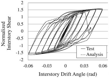
Figure description:
Normalized Interstory Shear vs. Interstory Drift Angle
Legend
- Test — color: black; symbol: Solid line
- Analysis — color: black; symbol: Dashed line
| Interstory Drift Angle (rad) | Test (Upper Shear) | Test (Lower Shear) | Analysis (Upper Shear) | Analysis (Lower Shear) |
|---|---|---|---|---|
| -0.06 | -1.65 | -1.65 | -1.60 | -1.60 |
| -0.05 | -1.60 | -1.45 | -1.55 | -1.50 |
| -0.04 | -1.52 | -1.10 | -1.48 | -1.30 |
| -0.03 | -1.40 | -0.85 | -1.35 | -1.25 |
| -0.02 | -1.22 | -0.60 | -1.25 | -1.05 |
| -0.01 | -0.95 | -0.30 | -1.00 | -0.95 |
| 0.00 | 0.20 | -0.20 | 0.90 | -0.90 |
| 0.01 | 0.30 | 0.95 | 0.95 | 1.00 |
| 0.02 | 0.60 | 1.22 | 1.05 | 1.25 |
| 0.03 | 0.85 | 1.40 | 1.25 | 1.35 |
| 0.04 | 1.10 | 1.52 | 1.30 | 1.48 |
| 0.05 | 1.45 | 1.60 | 1.50 | 1.55 |
| 0.06 | 1.65 | 1.65 | 1.60 | 1.60 |
Notes: The chart displays hysteresis loops comparing experimental test data with analytical predictions. The experimental data (Test exhibits significant pinching behavior compared to the analytical model (Analysis, which shows broader loops indicating higher energy dissipation. The data table represents the envelope and key transition points of the outermost hysteresis loop.))
Fig. C-12.3 Testing versus FEA analysis for frame modeled with all material nonlinearity in the Yield-Link elements.
Borrowing from the bolted unstiffened and stiffened extended end-plate moment connection provisions in Chapter 6, Step 18 provides an analogous design procedure for checking the column flanges for flexural yielding based on the maximum probable tensile strength of the Yield-Link.
If the design strength of the column web or flange without continuity plates or stiffeners is insufficient to support the maximum probable tensile strength of the Yield-Links, the design requirements for the stiffeners or continuity plates are in Step 19. Fillet welds are permitted at both column web and flange connections to the continuity plates or stiffeners.