Step 1. Compute the probable maximum moment at the plastic hinge, , in accordance with Section 2.4.3.
For beams with an RBS cutout, is determined using Equation 2.4-2 and defined in Equation 5.7-4.
For beams without an RBS cutout, and plastic section modulus of the beam.
Step 2. Determine the location of the plastic hinge (see Figure 10.10).
For beams with an RBS cutout, the plastic hinge shall be assumed to occur at the center of the reduced section of beam flange.
For beams without an RBS cutout, the plastic hinge shall be assumed to occur at a distance from the outside face of the collar, where is the beam depth.
Step 3. Compute the shear force at the plastic hinge, , in accordance with Section 2.4.4.
Step 4. Compute the moment at the collar bolts for each beam:
(10.7-1)
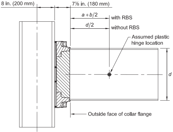
Figure description:
Diagram Type: Structural engineering schematic of a beam-to-column connection showing plastic hinge locations.
Key Entities & Dimensions:
- Column: Left vertical element with a width dimension indicated at 8 in. (200 mm from the centerline.
- Beam: Right horizontal element with depth .
- Collar Flange: Interface component between the beam and column.
- Assumed Plastic Hinge Location: Designated by a central dot on the beam's neutral axis.
- Distance to Hinge (from outside face of collar flange:
- With RBS (Reduced Beam Section:
- Without RBS:
- Fixed Offset: 7⅛ in. (180 mm from the column face to the outside face of the collar flange.
Fig. 10.10. Assumed plastic hinge location.
where
where
Step 5. The following relationship shall be satisfied for the collar bolt tensile strength:
(10.7-4)
(10.7-4M)
where
(10.7-5)
User Note: For 1¼-in.- (31-mm-) diameter ASTM A574 bolts, the value of is the same as for 1¼-in.- (31-mm-) diameter ASTM F3125/F3125M Grade A490 or A490M bolts and has a value of 102 kips (450 000 N).
Step 6. Compute , the probable maximum shear at the collar bolts taken equal to calculated in accordance with Section 2.4.4, plus any additional gravity loads between the plastic hinge and center of the collar flange, using the load combination in Section 2.4.4. Confirm that is less than the slip-critical, Class A, bolt design strength in accordance with the AISC Specification and using a resistance factor, , of 1.00 .
Step 7. Compute , the probable maximum shear at the face of collar flange taken equal to calculated in accordance with Section 2.4.4, plus any additional gravity loads between the plastic hinge and outside face of the collar flange, using the load combination in Section 2.4.4.
The required shear strength of the beam shall be taken equal to . Check the design shear strength of the beam in accordance with the AISC Specification.
Step 8. Determine the required size of the fillet weld connecting the beam web to the collar web extension (CWX) using the following relationship:
(10.7-6)
where
Step 9. Compute , the probable maximum shear at the face of column, taken equal to calculated in accordance with Section 2.4.4, plus shear due to gravity load between the plastic hinge and the face of the column, using the load combination in Section 2.4.4.
Determine the size of fillet weld connecting the collar corner assemblies to the column using the following relationship:
where
total length of available fillet weld at collar corner assembly, in. (mm), taken as 72 in. (1800 mm) for W30 (W760) sections; 66 in. (1700 mm) for W27 (W690) sections; 60 in. (1500 mm) for W24 (W610) sections; 54 in. (1400 mm) for W21 (W530) sections; and 48 in. (1200 mm) for W18 (W460) sections
fillet weld size required to join collar corner assembly to column, in. (mm)
Step 10. Check the design shear strength of the beam in accordance with the AISC Specification.
The required shear strength of the beam shall be taken as .
Step 11: Check the panel zone in accordance with Section 2.7.
When computing the required panel-zone shear strength, the depth of the panel zone shall be taken as the depth of the beam.
The design panel-zone shear strength, , shall be computed as
where
(10.7-9)
= specified minimum yield stress, ksi (MPa)
= depth of column, in. (mm)
effective depth of collar corner assembly leg, taken as in. (89 mm)
wall thickness of HSS or built-up box column, in. (mm)
CC
= effective thickness of collar corner assembly leg, taken as 1/2 in. (13 mm)
User Note: If the required strength exceeds the design strength, the designer may increase the column section and/or decrease the beam section strength, assuring that all other design criteria are met.
Step 12. Check the column-beam moment ratio as follows:
- (a) For SMF, check the column-beam moment ratio in accordance with Section 2.8 considering simultaneous development of the probable maximum moments in the moment-connected beams framing into all sides of the ConXL node.
For the purpose of satisfying this requirement, it is permitted to take the yield strength of the column material as the specified and to consider the full composite behavior of the column for axial load and flexural action.
User Note: The specified value of may be different than the specified minimum value associated with the grade of steel if project specifications require a higher minimum yield strength.
The value of about each axis shall be taken as
where
= height of story above node, in. (mm)
=plastic moment of column above node, about the axis under consideration considering simultaneous axial loading and loading about the transverse axis, kip-in. (N-mm)
- plastic moment of column below node, about the axis under consideration considering simultaneous axial loading and loading about the transverse axis, kip-in. (N-mm)
For sections with equal properties about both axes, it is permitted to take and as:
where
axial load acting on column at section under consideration in accordance with the applicable load combination specified by the building code, but not considering the amplified seismic load, kips (N)
plastic section modulus of the column about either axis, in.
specified compressive strength of concrete fill, ksi (MPa)
- (b) For IMF, check column-beam moment ratio in accordance with Section 2.8.