Step 1. Compute the probable maximum moment at the plastic hinge, , in accordance with Section 2.4.3, where plastic section modulus of the beam, in. .
Step 2. Determine the distance of the plastic hinge from the face of the column, , where width of the shear plate, in. (mm).
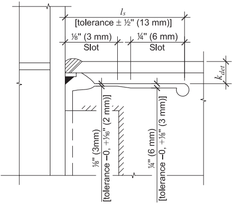
Figure description:
- Subject: Slot widths and tolerances for a structural connection (likely a steel beam-to-column joint.
- Key Dimensions & Tolerances:
- Total Length (: Tolerance (13 mm.
- First Slot: (3 mm width; tolerance (2 mm.
- Second Slot: (6 mm width; tolerance (3 mm.
- Vertical Offset (: Distance from the top of the horizontal member to the slot center-line.
- Entities: Column (left, horizontal beam/plate assembly, weld (indicated by hatched triangle, and specified slot configurations.
Fig. 14.3. Slot widths and tolerances.
Step 3. Compute the shear force at the plastic hinge, , at each end of the beam in accordance with Section 2.4.4.
Step 4. Compute the probable maximum moment at the face of the column, , in accordance with Section 2.4.5.
User Note: is needed to check continuity plate requirements (Step 11) and panel-zone requirements (Step 12).
Step 5. Design the beam web slots. The beam slot length, , shall be the least of the following within :
(14.7-1) (14.7-2)
(14.7-3)
(14.7-4)
where
- modulus of elasticity of steel
- specified minimum yield stress of beam, ksi (MPa)
- ratio of expected yield stress to specified minimum yield stress
- width of beam flange, in. (mm)
- = depth of beam, in. (mm)
- = half the clear span length of beam, in. (mm)
- = width of the shear plate, in. (mm)
- = thickness of beam flange, in. (mm)
Step 6. Design the shear plate. Steel with a specified minimum yield stress of 50 ksi (345 MPa) shall be used. The shear plate width shall not be greater than half the length of the beam web slot or 6 in. (150 mm) but not less than one-third the beam slot length. The height, , of the shear plate is determined as
| h=T-2 in. ± 1 in. | (14.7-5) |
| h=T-50 mm ± 25 mm | (14.7-5M) |
where is defined in the AISC Manual for wide-flange shapes. The minimum shear plate thickness shall be equal to at least two-thirds of the beam web thickness but not less than in. (10 mm).
The minimum required shear plate thickness, , is based upon the additional moment due to shear amplification from the end of the shear plate to the face of the column.
Use the plate elastic section modulus to conservatively compute the shear plate minimum thickness:
where
plastic modulus of the beam, in.
Step 7. Design the shear plate-to-beam web weld. The shear plate shall be welded to the beam web with an eccentrically loaded fillet weld group. The weld shall be designed to resist and to account for the resulting eccentricity, . These values are determined as follows:
(14.7-7)
(14.7-8)
(14.7-9)
where
- moment resisted by the shear plate, kip-in. (N-mm)
- shear resisted by the shear plate, kips (N)
(14.7-10)
User Note: The AISCMannual design tables for "Eccentrically Loaded Weld Groups" may be used to design the shear plate-to-beam web fillet weld. Use the height and width of the shear plate and the shear eccentricity, , as shown in Figure 14.4, to determine the weld design table coefficients.
Step 8. Design the shear plate-to-column flange weld.
The required strength of the weld connecting the shear plate to the column flange shall be equal to the nominal strength of the eccentrically loaded weld group as calculated according to Step 7.
Step 9. Select the high strength pretensioned bolts in standard holes for the shear plate-to-beam web connection to serve as both erection bolts and to stabilize the beam web from lateral buckling at the column flange. These bolts shall have a maximum bolt spacing of 6 in. (150 mm) on center over the full height of the plate. The diameter of the bolts shall be equal to or greater than the thickness of the beam web.
Step 10. Check the design shear strength of the beam in accordance with the AISC Specification.
The required shear strength of the beam shall be determined in accordance with Section 2.5.
Step 11. Check continuity plate requirements in accordance with Section 2.6.
Step 12. Check the panel zone in accordance with Section 2.7.
Step 13. Check the column-beam moment ratio in accordance with Section 2.8.
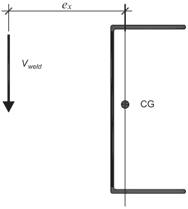
Figure description:
- Weld Pattern: C-shaped configuration.
- : Applied vertical load.
- : Horizontal eccentricity distance from the load to the center of gravity.
- CG: Center of gravity of the weld group.
Fig. 14.4. Eccentrically loaded weld group.