AISC 358-22, Prequalified Connections for Special and Intermediate Steel Moment Frames for Seismic Applications
Last Updated 29 Oct 2026
Hover any section to copy its link or text, ask Copilot about it, or bookmark it.
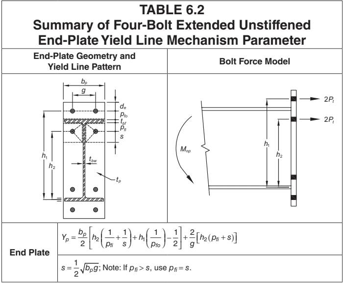
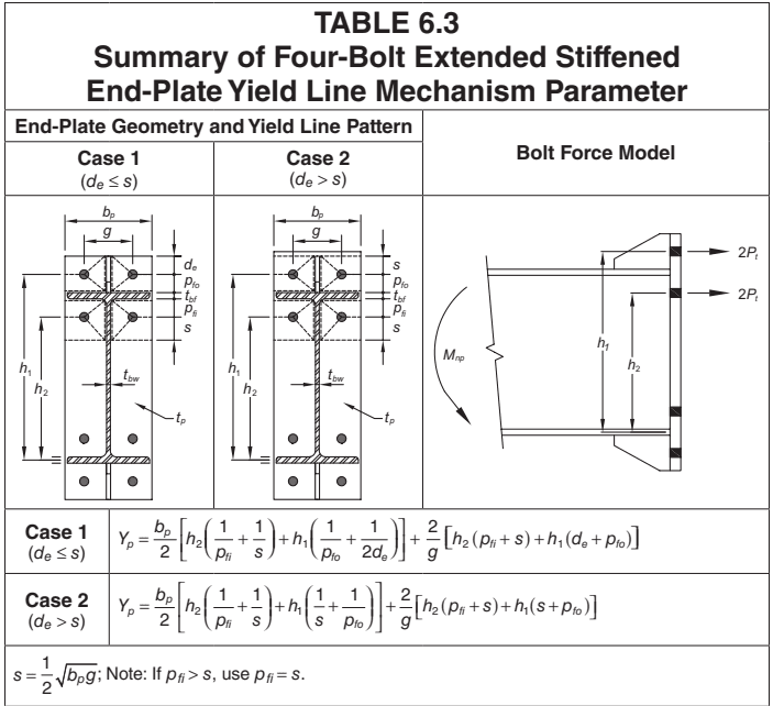
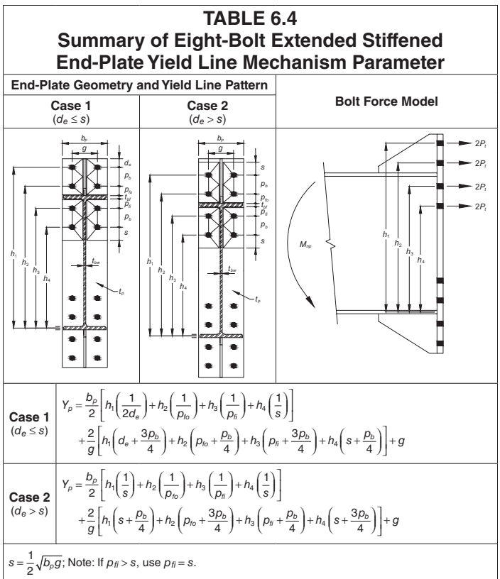
Connection geometry is shown in Figures 6.2, 6.3, and 6.4 for the 4E, 4ES, and 8ES connections, respectively.
6.7.1 End Plate and Bolt Design
Step 1. Compute the probable maximum moment at the plastic hinge, Mpr, in accordance with Section 2.4.3, where Ze=Zb= the plastic section modulus of the beam.
Step 2. Determine the distance of the plastic hinge from the face of the column, Sh.
For an unstiffened connection (4E)
Sh= the lesser of d/2 or 3bf (6.7-1)
where
bf= width of beam flange, in. (mm)
d= depth of beam, in. (mm)
For a stiffened connection (4ES, 8ES)
Sh=Lst+tp (6.7-2)
where
Lsttp= length of end-plate stiffener as shown in Figure 6.5, in. (mm) = thickness of end plate, in. (mm)
Step 3. Compute the shear force at the plastic hinge, Vh, in accordance with Section 2.4.4.
Step 4. Compute the probable maximum moment at the face of the column, Mf, in accordance with Section 2.4.5.
Step 5. Select one of the three end-plate moment connection configurations and establish preliminary values for the connection geometry (g, pfi, pfo, pb, g, hi, etc.) and bolt grade.
Step 6. Determine the required bolt diameter, db, req , using one of the following expressions.
For four-bolt connections (4E, 4ES)
db,req=πϕnFnt(h1+h2)2Mf
(6.7-3)
For eight-bolt connections (8ES)
db,req=πϕnFnt(h1+h2+h3+h4)2Mf (6.7-4)
where
Fnt= nominal tensile stress of bolt from the AISc Specification, ksi (MPa)
hi= distance from centerline of the beam compression flange to the centerline of i th tension bolt line, in. (mm)
Step 7. Select a trial bolt diameter, db, not less than that required in Section 6.7.1, Step 6.
FypYp= specified minimum yield stress of end-plate material, ksi (Mpa) = end-plate yield line mechanism parameter from Tables 6.2,6.3, or 6.4, in. (mm)
Step 9. Select an end-plate thickness, tp, not less than the required value.
Step 10. Compute the factored beam flange force, Ffu :
Ffiu=d−tbfMf
(6.7-6)
where
d = depth of beam, in. (mm)
tbf = thickness of beam flange, in. (mm)
Step 11. Check shear yielding of the extended portion of the four-bolt extended uns-tiffened end plate (4E):
Ffu/2≤ϕd(0.6)Fypbptp (6.7-7)
where bp is the width of the end plate, in. (mm), to be taken as not greater than the width of the beam flange plus 1 in. (25 mm).
If Equation 6.7-7 is not satisfied, increase the end-plate thickness or increase the yield stress of the end-plate material.
Figure description:
TABLE 6.2: Summary of Four-Bolt Extended Unstiffened End-Plate Yield Line Mechanism Parameter
End-Plate Geometry and Yield Line Pattern Variables:
bp: Width of the end plate
g: Bolt gage (horizontal distance between bolts
de: Distance from top edge to the first bolt row
pfo: Distance from beam flange face to the outer bolt row
tbf: Thickness of the beam flange
pfi: Distance from beam flange face to the inner bolt row
s: Yield line distance parameter
tbw: Thickness of the beam web
tp: Thickness of the end plate
h1,h2: Vertical distances from the center of the compression flange to the tension bolt rows
Bolt Force Model Variables:
Mnp: Moment capacity
2Pt: Tension force applied at each bolt row level
Step 12. Check shear rupture of the extended portion of the end plate in the four-bolt extended unstiffened end plate (4E):
Ffu/2≤ϕn(0.6)FupAn
where
AnFupdb= net area of end plate =tp[bp−2(db+81)] when standard holes are used, in. 2=tp[bp−2(db+3)] when standard holes are used, mm 2= specified minimum tensile stress of end-plate material, ksi (MPa) = diameter of bolt, in. (mm)
Step 13. If using either the four-bolt extended stiffened end plate (4ES) or the eight-bolt extended stiffened end-plate (8ES) connection, select the end-plate stiffener thickness, and design the stiffener-to-beam flange and stiffener-to-end-plate welds.
ts≥tbw(FysFyb)
(6.7-9)
where
FybFystbwts= specified minimum yield stress of beam material, ksi (MPa) = specified minimum yield stress of stiffener material, ksi (MPa) = thickness of beam web, in. (mm) = end-plate stiffener thickness, in. (mm)
The stiffener geometry shall conform to the requirements of Section 6.6.4. In addition, to prevent local buckling of the stiffener plate, the following width-to-thickness criterion shall be satisfied:
tshst≤0.56FysE
(6.7-10)
where hst is the height of the stiffener, in. (mm), equal to the height of the end plate from the outside face of the beam flange to the end of the end plate.
The stiffener-to-beam-flange and stiffener-to-end-plate welds shall be designed to develop the stiffener plate in shear at the beam flange and in tension at the end plate. Either fillet or CJP groove welds are suitable for the weld of the stiffener plate to the beam flange. CJP groove welds shall be used for the stiffener-to-end-plate weld. If the stiffener is 3/8 in. (10 mm) thick or less, double-sided fillet welds are permitted.
Step 14. Check the design shear strength of the beam in accordance with the AISC Specification.
The required shear strength of the beam shall be determined in accordance with Section 2.5.
Step 15. Determine the required shear strength of the beam-to-column connection. The required shear strength of the beam-to-column connection, Vu, shall be taken equal to the required shear strength of the beam.
Step 16. The bolt shear rupture strength of the connection is provided by the bolts at one (compression) flange; thus
Vu≤ϕnnbFnvAb
(6.7-11)
where
Ab= nominal gross area of bolt, in. 2(mm2)
Fnv= nominal shear stress of bolt from the AISC Specification, ksi (MPa)
nb= number of bolts at compression flange
= 4 for 4E and 4ES connections
= 8 for 8ES connections
Step 17. Check bolt bearing and tearout failure of the end plate and column flange:
Vu≤ϕnΣrni
(6.7-12)
where
rni=1.2lctFu<2.4dbtFu for each bolt
and
Fu= specified minimum tensile strength of end plate or column flange material, ksi (MPa)
lc= clear distance, in direction of force, between edge of the hole and edge of the adjacent hole or edge of material, in. (mm)
t = thickness of end plate or column flange, in. (mm)
Step 18. Design the flange-to-end-plate and web-to-end-plate welds using the requirements of Section 6.6.6.
6.7.2 Column-Side Design
Step 1. Check the column flange for flexural yielding:
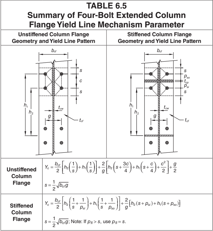
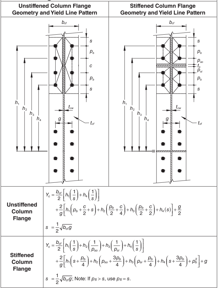
Yc= unstiffened column flange yield line mechanism parameter from Table 6.5 or Table 6.6, in. (mm)
tcf= thickness of column flange, in. (mm)
User Note: The yield line mechanism parameters, Yc, from Table 6.5 and Table 6.6 assume that the distance from the top-most bolt line to the top of the column shall be greater than the dimension s.
If Equation 6.7-13 is not satisfied, increase the column size or add continuity plates.
If continuity plates are added, check Equation 6.7-13 using Yc for the stiffened column flange from Tables 6.5 and 6.6.
Figure description:
TABLE 6.5Summary of Four-Bolt Extended Column Flange Yield Line Mechanism Parameter
Feature
Unstiffened Column Flange
Stiffened Column Flange
Geometry and Yield Line Pattern
Diagram showing four bolts with dimensions: bcf, s, c, h1, h2, g, tcw, tcf. Yield lines form a diamond pattern between the bolt rows.
Diagram showing four bolts with stiffener (continuity plate. Dimensions: bcf, s, pso, tcp, psi, h1, h2, g, tcw, tcf.)
Step 2. If continuity plates are required for column flange flexural yielding, determine the required stiffener force.
The column flange design flexural strength is
ϕdMcf=ϕdFycYctcf2
(6.7-14)
where Yc is the unstiffened column yield line mechanism parameter from Table 6.5 or Table 6.6, in. (mm). Therefore, the equivalent column flange design force is
ϕdRn=(d−tbf)ϕdMcf
(6.7-15)
TABLE 6.6
Summary of Eight-Bolt Extended Column
Flange Yield Line Mechanism Parameter
Figure description:
TABLE 6.6Summary of Eight-Bolt Extended Column Flange Yield Line Mechanism Parameter
w= leg size of double fillet weld if used in the beam flange-to-endplate weld, in. (mm)
If the strength requirement of Equation 6.7-18 is not satisfied, then column web con-tinuity plates are required.
Step 5. If continuity plates are required for any of the column side limit states, the required strength is
Fsu=Ffu−min(ϕRn)
(6.7-22)
where min(ϕRn) is the minimum design strength value from Section 6.7.2, Step 2 (column flange local bending), Step 3 (column web local yielding), and Step 4 (column web local crippling)
The design of the continuity plates shall also conform to AISC Seismic Provisions Chapter E, and the welds shall be designed in accordance with Section 6.4(3).
Step 6. Check the panel zone in accordance with Section 2.7.
Step 7. Check the column-beam moment ratio in accordance with Section 2.8.