Extended end-plate moment connections are prequalified for use in special moment frame (SMF) and intermediate moment frame (IMF) systems.
Exception: Extended end-plate moment connections with concrete structural slabs are prequalified only if
- (1) In addition to the limitations of Section 6.3, the nominal beam depth is not less than 24 in. (600 mm);
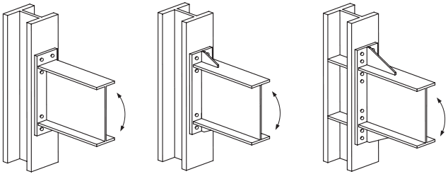
Figure description:
Key information extracted from the structural diagrams:
- (a Four-bolt unstiffened (4E: Beam-to-column connection using an end plate with four bolts and no reinforcing stiffeners.
- (b Four-bolt stiffened (4ES: Similar to 4E but includes a triangular gusset stiffener welded to the top of the beam flange and end plate.
- (c Eight-bolt stiffened (8ES: A heavier connection using eight bolts, triangular gusset stiffeners, and internal column web continuity plates.
- Key Entities: Steel I-beams, vertical columns, bolted end plates, gusset stiffeners, and continuity plates.
- Functional Detail: Curved arrows indicate the assembly is designed to resist rotational moments at the joint.
(a) Four-bolt unstiffened, (b) Four-bolt stiffened, (c) Eight-bolt stiffened,
Fig. 6.1. Extended end-plate configurations.
| Four-Bolt Unstiffened (4E) | Four-Bolt Stiffened (4ES) | Eight-Bolt Stiffened (8ES) | ||||
|---|---|---|---|---|---|---|
| Parameter | Maximum in. (mm) | Minimum in. (mm) | Maximum in. (mm) | Minimum in. (mm) | Maximum in. (mm) | Minimum in. (mm) |
| tbf | ¾ (19) | ⅜ (10) | ¾ (19) | ⅜ (10) | 1 (25) | 9⁄16 (14) |
| bbf | 9¼ (230) | 6 (150) | 9 (230) | 6 (150) | 12¼ (310) | 7½ (190) |
| d | 24 (600) | 13¾ (350) | 24 (600) | 13¾ (350) | 36 (910) | 18 (460) |
| tp | 2¼ (57) | ½ (13) | 1½ (38) | ½ (13) | 2½ (64) | ¾ (19) |
| bp | 10¾ (270) | 7 (180) | 10¾ (270) | 7 (180) | 15 (380) | 9 (230) |
| g | 6 (150) | 4 (100) | 6 (150) | 3¾ (83) | 6 (150) | 5 (130) |
| pfi, pfo | 4½ (110) | 1½ (38) | 5½ (140) | 1¾ (44) | 2 (51) | 1⅝ (41) |
| pb | – | – | – | – | 3¾ (95) | 3½ (89) |
width of beam flange, in. (mm)
- width of end plate, in. (mm)
- depth of connecting beam, in. (mm)
- g = horizontal distance between bolts, in. (mm)
- vertical distance between the inner and outer row of bolts in an 8ES connection, in. (mm)
- vertical distance from the inside of a beam tension flange to the nearest inside bolt row, in. (mm)
- vertical distance from the outside of a beam tension flange to the nearest outside bolt row, in. (mm)
- thickness of beam flange, in. (mm)
- = thickness of end plate, in. (mm)
- (2) There are no shear connectors within 1.5 times the beam depth from the face of the connected column flange; and
- (3) The concrete slab is isolated in accordance with Section 2.3.4.