The DuraFuse Frames connection utilizes plates to connect beams to columns. For I-shaped columns, the column has cover plates on each side that are fillet welded to the column flanges [Figure 15.1(a) and (b)]. For box or HSS columns, the sides of the column may function as the cover plates [Figure 15.1(c)]. Four external continuity plates that extend past the face of the column are fillet welded to the column cover plates. The column has a single-plate shear connection with horizontal slotted holes that is fillet welded to the column face. The beam web, with standard holes, is attached to the single-plate shear connection with pretensioned bolts. The beam flanges are attached to the external continuity plates via top plates and a fuse plate (Figure 15.1). The beam flanges and external continuity plates have standard holes, while the top plates and fuse plate have oversized holes. The fuse plate is proportioned such that certain regions of the plate experience shear yielding when the connection is subjected to severe earthquake loading. The fuse plate is bolted in place so that it could be removed and replaced following a severe earthquake. The top plates are intended to experience minimal yielding such that they would not require repair following a severe earthquake. The various plates in the connection are proportioned such that the beam remains essentially elastic.
The inelastic mechanism is the same for DuraFuse Frames biaxial configurations (Figure 15.2). Fuse plates are proportioned to be the yielding element. The other plates and welds in the connections are capacity-based design elements, sized in accordance with the AISC Specification and the AISC Seismic Provisions using the maximum forces that can be delivered by the fuse plates.
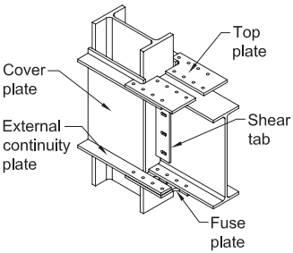
Figure description:
- Configuration: One-sided structural steel connection with wide-flange beam and column.
- Key Components:
- Wide-flange column: Vertical primary support.
- Wide-flange beam: Horizontal structural member.
- Cover plate: Reinforcement plate on the column.
- External continuity plate: Horizontal plates aligned with beam flanges to transfer loads across the column.
- Top plate: Bolted connection at the top flange of the beam.
- Shear tab: Vertical plate for connecting the beam web.
- Fuse plate: Specialized connection plate at the bottom flange, likely designed for seismic energy dissipation.
(a) One-sided configuration with wide-flange beam and column
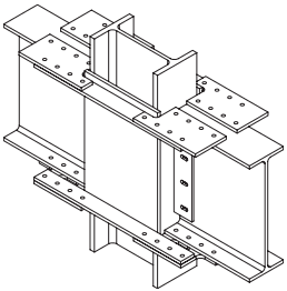
Figure description:
- Type: Two-sided structural steel beam-to-column connection.
- Key Entities:
- One central vertical wide-flange column.
- Two horizontal wide-flange beams connected to the column flanges.
- Components:
- Top Flange Plates: Bolted to the top of both beam flanges.
- Bottom Flange Plates: Long plates bolted to the bottom of the beam flanges, passing across the column.
- Shear Tabs: Vertical plates bolted to the beam webs and attached to the column flange to transfer shear forces.
- Fastening: Multi-bolt configurations on all flange and web plates.
(b) Two-sided configuration with wide-flange beams and column
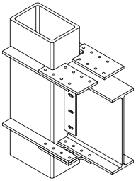
Figure description:
Subject: Structural steel beam-to-column connection diagram.
Key Entities:
- HSS Column: A vertical rectangular Hollow Structural Section.
- Wide-Flange Beam: A horizontal I-beam connected to the column face.
- Flange Connection Plates: Top and bottom bolted plates that join the beam flanges to the column assembly.
- Shear Tab: A vertical bolted plate connecting the beam web to the column.
- External Diaphragm Plates: Horizontal plates wrapping around the HSS column at the top and bottom flange levels to reinforce the connection and transfer moments.
- Bolts: Fasteners shown in the flange plates and shear tab.
(c) Wide-flange beam with HSS column
Fig. 15.1. DuraFuse Frames connection configurations. (Two-sided HSS column connection permitted but not shown.)