The SidePlate moment connection is prequalified for use in special moment frame (SMF) and intermediate moment frame (IMF) systems within the limits of these provisions. The SidePlate moment connections are prequalified for use in
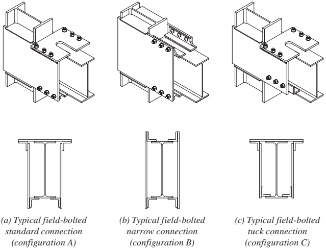
Figure description:
Key Entities & Information:
- Subject: SidePlate field-bolted moment connection configurations for Special Moment Frames (SMF and Intermediate Moment Frames (IMF.
- Components: Steel I-beams (columns and beams, side plates, connecting angles/brackets, and structural bolts.
- Configurations:
- (a Standard Connection (Configuration A: Features a wide top plate bolted across the top flange and side plates bolted to bottom brackets.
- (b Narrow Connection (Configuration B: Utilizes side-mounted angles for bolting, suited for narrower structural profiles.
- (c Tuck Connection (Configuration C: Similar to the standard setup but with a "tucked" bottom angle configuration for specific clearance or load requirements.
Fig. 11.3. SidePlate field-bolted connection configurations.
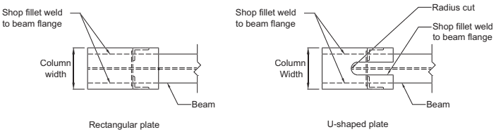
Figure description:
Cover Plate Configurations
- Rectangular plate:
- Features shop fillet welds to the beam flange.
- Width corresponds to the column width.
- U-shaped plate:
- Features shop fillet welds to the beam flange along exterior and interior edges.
- Includes a central radius cut.
- Width corresponds to the column width.
Cover Plate Configurations
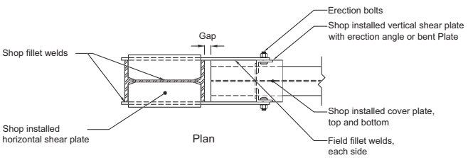
Figure description:
Plan Diagram: Cover Plate Configurations
- Key Components:
- Plates: Shop installed horizontal shear plate, shop installed vertical shear plate (with erection angle or bent plate, and shop installed cover plates (top and bottom.
- Fasteners: Erection bolts.
- Welds: Shop fillet welds and field fillet welds (each side.
- Structural Detail: Includes a designated "Gap" between structural sections.
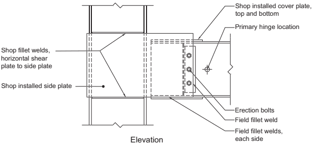
Figure description:
Image Type: Engineering Diagram (Elevation View Subject: Wide-flange beam to wide-flange column connection detail
Key Components & Details:
- Column & Beam: Wide-flange structural members.
- Side Plate: Shop-installed side plate attached to the column.
- Cover Plates: Shop-installed cover plates on top and bottom of the beam connection.
- Shear Plate: Horizontal shear plate connected to side plate via shop fillet welds.
- Hinge: Primary hinge location indicated on the beam web.
- Fasteners: Erection bolts used for initial positioning.
- Field Welds:
- Field fillet weld at the vertical edge of the connection.
- Field fillet welds on each side of the beam flange/cover plate interface.
(a) Typical wide-flange beam to wide-flange column—detail, plan, and elevation views
Fig. 11.4. (a) SidePlate uniaxial field-welded configuration geometry and major components.
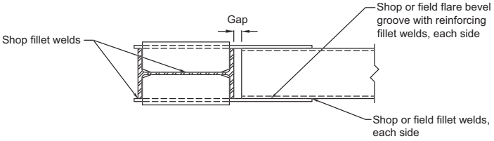
Figure description:
- Subject: Plan view of an HSS beam connection to a wide-flange column.
- Key Entities:
- HSS Beam: Hollow Structural Section member.
- Wide-Flange Column: Structural steel column with side plates attached to its flanges.
- Side Plates: Used to bridge the connection between the column and the beam.
- Technical Details:
- Gap: Specified spacing between the column flange and the end of the HSS beam.
- Welding Specifications:
- Shop fillet welds: Connect the column web and flanges to the side plates.
- Flare bevel groove welds: Shop or field applied with reinforcing fillet welds along each side of the HSS beam to the side plates.
- Terminal fillet welds: Shop or field fillet welds at the ends of the side plates against the HSS beam.
(b) HSS beam without cover plates to wide-flange column with the same flange width—plan view
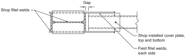
Figure description:
Structural Diagram: HSS Beam to Wide-Flange Column Connection (Plan View
Key Components:
- Wide-Flange Column: Shown in cross-section on the left.
- HSS Beam: Extends to the right, connected via cover plates.
- Shop Installed Cover Plates: Located at the top and bottom of the HSS beam.
- Shop Fillet Welds: Secure the connection components to the column flanges and web.
- Field Fillet Welds: Applied to each side to join the beam/cover plate assembly to the column connection.
- Gap: Specified spacing between the end of the HSS beam and the column face.
(c) HSS beam to wide-flange column—plan view
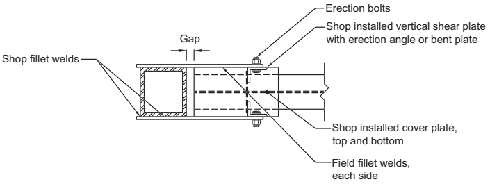
Figure description:
Diagram Type: Plan view of a Wide-flange beam to built-up box column connection.
Key Entities & Components:
- Built-up box column: Primary vertical support, featuring shop fillet welds.
- Wide-flange beam: Horizontal member connecting to the column.
- Cover plates (Top and Bottom: Shop-installed on the column and secured to the beam flanges with field fillet welds on each side.
- Vertical shear plate: Shop-installed component with an erection angle or bent plate for beam attachment.
- Erection bolts: Fasteners used for temporary positioning during assembly.
- Gap: Clearance maintained between the face of the box column and the end of the wide-flange beam.
- Welding: Utilizes both shop fillet welds (at column components and field fillet welds (to secure the beam.
(d) Wide-flange beam to built-up box column—plan view
Fig. 11.4. (b–d) SidePlate uniaxial field-welded configuration geometry and major components.
planar moment-resisting frames and orthogonal intersecting moment-resisting frames (biaxial configurations, capable of connecting up to four beams at a column as illustrated in Figures 11.5 and 11.6). The SidePlate connection is exempt from the requirements of Section 2.3.4.