Step 1. Choose trial frame beam and column section combinations that satisfy geometric compatibility based on Equation 11.4-1a (11.4-1aM) or 11.4-1b (11.4-1bM).
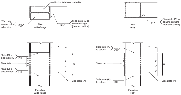
Figure description:
Fig. 11.14: One-sided SidePlate moment connection (A-type, column shop detail
Key Components & Dimensions:
- Side Plate {A}: External plates attached to the column; vertical dimension B, cantilever extension dimension A.
- Horizontal Shear Plate {D}: Internal reinforcement plate within the column.
- Shear Tab: Connected to the side of the column for beam web attachment.
- Column Types: Details provided for both Wide-flange (Plan and Elevation and HSS (Plan and Elevation sections.))
Weld Specifications:
- {1}: Fillet welds connecting Plate {D} to Side plate {A} and Side plate {A} to the column.
- {2}: CJP (Complete Joint Penetration groove welds connecting Side plate {A} to column flange/corners (noted as demand critical.
- {3}: Fillet welds for internal horizontal shear plate (web only, unless noted.
Fig. 11.14. One-sided SidePlate moment connection (A-type), column shop detail.
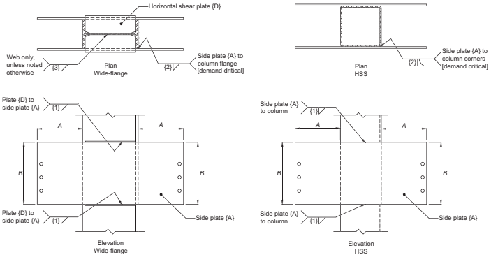
Figure description:
Key Entities and Details:
- Connection Type: Two-sided SidePlate moment connection (B-type.
- Column Types: Wide-flange (I-shape and HSS (square hollow structural section.
- Major Components:
- Side Plate {A}: Large vertical reinforcement plates attached to either side of the column. Dimensions are marked as A (width from column face and B (height.))
- Horizontal Shear Plate {D}: Internal reinforcement plate used specifically in the wide-flange column detail.
- Weld Details:
- Weld {1}: Fillet welds connecting Side Plate {A} to the column or Shear Plate {D}.
- Weld {2}: Demand-critical bevel/groove welds connecting Side Plate {A} to column flanges (wide-flange or column corners (HSS.
- Weld {3}: Fillet weld on the column web (wide-flange plan only.
- Layout:
- Plan Views: Show the cross-sectional arrangement and internal plates.
- Elevation Views: Show the vertical profile of the Side Plates and bolt hole patterns for beam connection.
Fig. 11.15. Two-sided SidePlate moment connection (B-type), column shop detail.
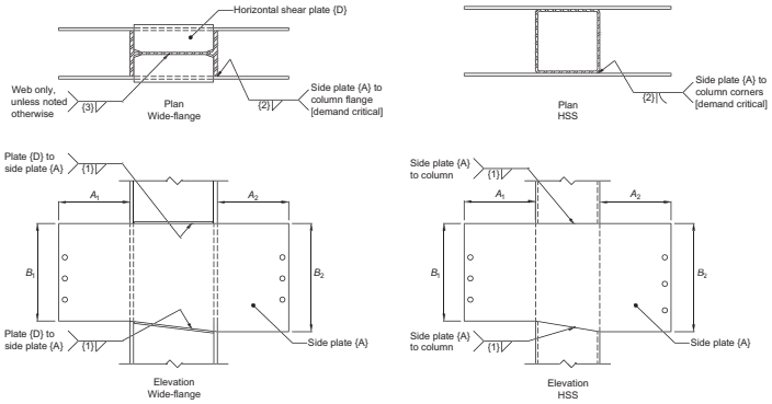
Figure description:
The image contains technical drawings for column shop details of two-sided SidePlate moment connections.
Key Entities and Components:
- Column Types:
- Wide-flange: B-type connection detail.
- HSS (Hollow Structural Section: C-type connection detail.
- Main Parts:
- Side plate {A}: Parallel plates attached to the sides of the column.
- Horizontal shear plate {D}: Plate between wide-flange column flanges (Wide-flange detail only.
- Dimensions:
- : Horizontal lengths of side plates extending from column faces.
- : Vertical depths of side plates.
- Welding Details:
- {1}: Fillet weld connecting Side plate {A} to Horizontal shear plate {D} or column.
- {2}: CJP (Complete Joint Penetration groove weld [demand critical connecting Side plate {A} to column flange/corners.
- {3}: Fillet weld for Horizontal shear plate {D} to wide-flange web.
- Views Provided:
- Plan Views: Top-down cross-section showing plate placement and column-to-plate welds.
- Elevation Views: Side view showing plate dimensions ( and and vertical bolt hole arrangements.
Fig. 11.16. Two-sided SidePlate moment connection (C-type), column shop detail.
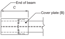
Figure description:
Diagram Type: Plan view of a beam assembly
Key Entities:
- End of beam: The starting reference point on the left.
- Cover plate {B}: A rectangular plate positioned at the end of the beam.
- Dimension C: The distance measured from the end of the beam to the opposite edge of the cover plate.
Plan Rectangular cover plate (B)
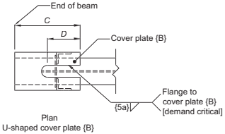
Figure description:
Entities and Details:
- Subject: Plan view of a U-shaped cover plate {B} attached to a beam.
- Key Dimensions:
- C: Distance from the 'End of beam' to the end of the cover plate.
- D: Length of the internal U-shaped cutout/notch in the cover plate.
- Components:
- End of beam: Leftmost reference line.
- Cover plate {B}: U-shaped plate fitted over the beam flange.
- Welding Specification:
- Weld type: Fillet weld indicated by the triangle symbol.
- Location: Flange to cover plate {B} interface.
- Note: {5a} reference; designated as [demand critical.
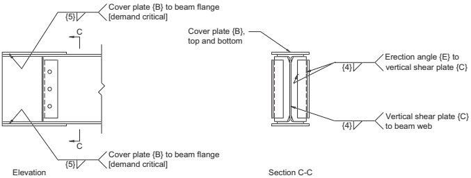
Figure description:
Figure 11.17: Beam shop detail (field welded
Elevation View
- Cover plate {B} to beam flange: Top and bottom connections using {5} fillet welds, noted as [demand critical.
- Beam assembly: Side view showing the beam flanges, web, and a vertical plate with three bolt holes.
Section C-C View
- Cover plate {B}: Positioned on the top and bottom of the beam flanges.
- Vertical shear plate {C} to beam web: Connected via {4} fillet welds.
- Erection angle {E} to vertical shear plate {C}: Connected via {4} fillet welds.
Fig. 11.17. Beam shop detail (field welded).
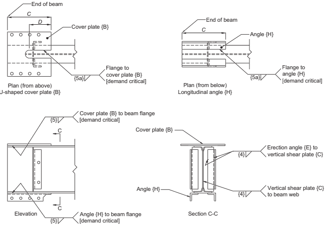
Figure description:
Image Type: Technical engineering shop detail drawings for structural beam connections.
Key Entities and Components:
- Cover Plate {B}: A J-shaped plate positioned on the top beam flange.
- Longitudinal Angle {H}: Positioned on the bottom beam flange.
- Vertical Shear Plate {C}: Welded to the beam web.
- Erection Angle {E}: Welded to the vertical shear plate {C}.
Critical Details:
- Demand Critical Welds: Connections between the beam flanges and both the cover plate {B} (welds {5}, {5a} and longitudinal angle {H} (welds {5}, {5a} are explicitly labeled as "demand critical."
- Standard Welds: Weld {4} is used for the erection angle to shear plate and shear plate to beam web connections.
- Dimensional References: Distances and establish the longitudinal positioning of plates and angles relative to the beam end.
- Views Provided:
- Plan (above: Shows J-shaped cover plate {B} configuration.
- Plan (below: Shows longitudinal angle {H} configuration.
- Elevation: Side profile of the beam end assembly.
- Section C-C: Cross-section showing the web, shear plate, and erection angle assembly.
Fig. 11.18. Beam shop detail, field-bolted standard (configuration A).
For SMF systems, check that the section combinations satisfy the preliminary column-beam moment ratio given by
(11.7-1)
where
specified minimum yield stress of beam, ksi (MPa)
specified minimum yield stress of column, ksi (MPa)
plastic section modulus of beam about -axis, in. (mm )
plastic section modulus of column about -axis, in.
Step 2. Approximate the effects on global frame performance of the increase in lateral stiffness and strength of the SidePlate moment connection due to beam hinge location and side plate stiffening in the mathematical elastic steel frame computer model by using a 100% rigid offset in the panel zone and by increasing the moment of
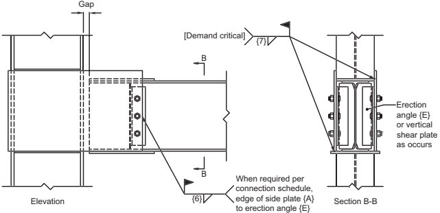
Figure description:
Subject: Technical drawing of a SidePlate moment connection (Elevation and Section B-B, field welded.
Key Entities and Details:
- Components: Column, beam, side plates, and erection angles (or vertical shear plates.
- Gap: Specified distance between the column flange and the side plate assembly.
- Welding:
- Demand Critical: Field welds indicated for structural integrity.
- Side Plate Connection: Weld symbol {6} specifies connecting the edge of side plate {A} to erection angle {E} as per the connection schedule.
- Section B-B: Illustrates the internal arrangement where the beam web is secured between erection angles/shear plates and the external side plates.
- Contextual Modeling: Instructions suggest using a 100% rigid offset in the panel zone to account for the increased lateral stiffness and strength of this specific connection type.
(a) Elevation and Section B-B, field welded
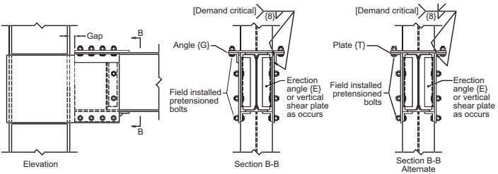
Figure description:
The image displays structural steel connection details in elevation and section views.
Key Components and Details
- Elevation View: Illustrates a beam-to-column connection with a specified Gap.
- Section B-B (Standard:
- Uses Angle {G} for the top connection.
- Features Field installed pretensioned bolts.
- Includes an Erection angle {E} or vertical shear plate.
- Specifies a [Demand critical weld with a size of {8}.
- Section B-B Alternate:
- Replaces Angle {G} with Plate {T}.
- Retains the same bolt, erection angle/plate, and welding specifications as the standard section.
- General Specifications:
- The connections are designated as field-bolted and field-welded configurations.
- Welding symbols indicate specific structural requirements for demand-critical joints.
(b) Elevation and Section B-B, field-bolted standard (configuration A)
Fig. 11.19. Beam-to-SidePlate field erection detail.
inertia, elastic section modulus, and plastic section modulus of the beam to approximately three times that of the beam for a distance of approximately 77% of the beam depth beyond the column face (approximately equal to the extension of the side plate beyond the face of the column), illustrated in Figure 11.22.
SMF beams that have a combination of shallow depth and heavy weight (i.e., beams with a relatively large flange area such as those found in the widest flange series of a particular nominal beam depth) require that the extension of the side plate {A} be increased up to the nominal depth of the beam, , for field-welded connections and for field-bolted connections.
User Note: This increase in extension of side plate {A} of the field-welded connection lengthens fillet weld {7}, thus limiting the extremes in the size of fillet weld {7}. Regardless of the extension of the side plate {A}, the plastic hinge occurs at a distance of d/3 and d/6 from the end of the side plates for the field-welded and field-bolted connections, respectively.
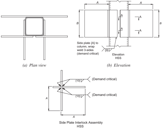
Figure description:
Key Entities and Information:
- Side Plate Connection (HSS: Features a Hollow Structural Section (HSS column with attached side plates.
- Dimensions: Side plates are defined by width A and height B.
- Weld {9}: Connects side plate {A} to the column using a 3-sided wrap weld; designated as Demand Critical.
- Weld {10}: Used at the Side Plate Interlock Assembly intersection; designated as Demand Critical.
- Structural Details:
- Plan View (a: Displays the cross-section of the HSS column and the orientation of the side plates.
- Elevation (b: Shows the vertical profile and section cuts (A-A.
- Side Plate Interlock Assembly: A detail showing the intersection of plates with leg lengths A.
- Functional Note: The extension of side plate {A} affects the length of fillet weld {7}. Plastic hinges occur at distances of d/3 (field-welded or d/6 (field-bolted from the end of the side plates.
(c) Side plate interlock assembly Section A-A
Fig. 11.20. Biaxial HSS column assembly shop detail.
Step 3. Confirm that the frame beams and columns satisfy all applicable building code requirements, including, but not limited to, stress or strength checks and design story drift checks.
Step 4. Confirm that the frame beam and column sizes comply with prequalification limitations in accordance with Section 11.3.
Step 5. Upon completion of the preliminary and/or final selection of lateral load-resisting frame beam and column member sizes using SidePlate connection technology, the engineer of record submits a computer model to SidePlate Systems Inc. In addition, the engineer of record shall submit the following additional information, as applicable:
factored gravity shear in moment frame beam resulting from the load combination of (where is the load factor determined by the applicable building code for live loads, but not less than 0.5), kips (N)
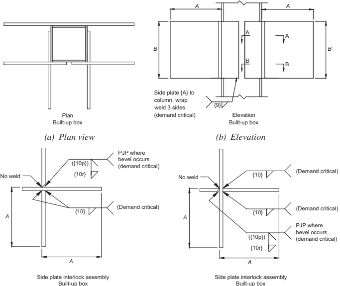
Figure description:
Structural engineering diagrams for a Side Plate interlock assembly on a built-up box column:
- (a Plan View: Shows the top-down configuration of the side plates and built-up box column.
- (b Elevation: Illustrates the vertical profile (height B, width A and specifies a demand-critical wrap weld on 3 sides ({9} connecting the side plate to the column.
- (c Section Views (A-A and B-B variations:
- Dimensions: Horizontal and vertical distances labeled as A.
- Weld Details:
- "No weld" zones at specific corners.
- Demand-critical welds labeled as {10}, {10p}, and {10r}.
- PJP (Partial Joint Penetration welds specified where bevels occur.
(c) Side plate interlock assembly section A-A
(d) Side plate interlock assembly section B-B
Fig. 11.21. Biaxial built-up box column assembly shop detail.
User Note: The load combination of 1.2D + f1L + 0.15S is in conformance with ASCE/SEI 7-22. When using the 2015 International Building Code, a factor of 0.7 must be used in lieu of the factor of 0.15 for S (snow) when the roof configuration is such that it does not shed snow off of the structure.
- (a) Factored gravity shear loads, V1 and/or V2, from gravity beams that are not in the plane of the moment frame, but connect to the exterior face of the side plate(s),
where
- (b) Factored gravity loads, and , from cantilever gravity beams that are not in the plane of the moment frame, but connect to the exterior face of the side plate(s),
where
- cantilever beam moment resulting from code applicable load combinations, kip-in. (N-mm)
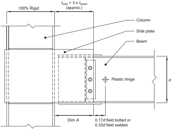
Figure description:
Diagram: Modeling of component stiffness for linear-elastic analysis
- Key Entities: Column, Side plate, Beam, Plastic hinge.
- Stiffness Zones:
- Column/Panel Zone: 100% Rigid.
- Side Plate Region: Total moment of inertia ( is approximately .
- Dimensions & Locations:
- Dim A: Length of the side plate extending from the column face.
- Plastic Hinge Location: Measured from the end of the side plate:
- for field bolted connections.
- for field welded connections.
- : Beam depth.
Fig. 11.22. Modeling of component stiffness for linear-elastic analysis.
User Note: Code applicable load combinations may need to include the following when looking at cantilever beams: and , which are in conformance with ASCE/SEI 7-22. When using the 2015 International Building Code, a factor of 0.7 must be used in lieu of the factor of 0.15 for (snow) when the roof configuration is such that it does not shed snow off of the structure.
- (c) Perpendicular amplified seismic lateral drag or chord axial forces, , transferred through the SidePlate connection,
where
amplified seismic drag or chord force resulting from the applicable building code, kips (N)
User Note: Where linear-elastic analysis is used to determine perpendicular collector or chord forces used to design the SidePlate connection, such forces should include the applicable load combinations specified by the building code, including consideration of the amplified seismic load, Ω₀. Where nonlinear analysis or capacity design is used, collector or chord forces determined from the analysis are used directly, without consideration of additional amplified seismic load.
- (d) In-plane factored chord axial forces, , transferred along the frame beam through the SidePlate connection, where
amplified seismic chord force resulting from applicable building code, kips (N)
Step 6. Upon completion of the mathematical model review and after additional information has been supplied by the engineer of record, SidePlate engineers provide project-specific connection designs. Strength demands used for the design of critical load-transfer elements (plates, welds, and columns) throughout the SidePlate beam-to-column connection and the column are determined by superimposing maximum probable moment, , at the known beam hinge location, then amplifying the moment demand to each critical design section based on the span geometry, as shown in Figure 11.9, and including additional moment due to gravity loads. For each of the design elements of the connection, the moment demand is calculated using Equation 11.7-2, and the associated shear demand is calculated as
(11.7-2)
where
maximum probable moment at the plastic hinge as defined in Section 2.4.3,
Equation 2.4-1, kip-in. (N-mm).
- maximum shear demand from probable maximum moment and factored gravity loads as defined in Section 2.4.4, Equation 2.4-3, kips (N).
- x = distance from plastic hinge location to centroid of connection element, in. (mm)
When calculating , the value of is provided by SidePlate as part of the connection design.
User Note: The value of for SidePlate connections is determined by testing and nonlinear analysis and ranges from 1.15 to 1.35 .
Step 7. SidePlate designs all connection elements according to the proprietary connection design procedures contained in the SidePlate Connection Design Software (version 16 for field-welded and version 17 for field-bolted connections). The version is clearly indicated on each page of calculations. The final design includes structural notes and details for the connections.
User Note: The procedure uses an ultimate strength design approach to size plates and welds, incorporating strength, plasticity, and fracture limits. For welds, an ultimate strength analysis incorporating the instantaneous center of rotation may be used as described in AISC Specification Section J2.4b. For bolt design, eccentric bolt group design methodology incorporating ultimate strength of the bolts is used. Refer to the Commentary for an in-depth discussion of the process.
In addition to the column web panel zone strength requirements, the column web shear strength shall be sufficient to resist the shear loads transferred at the top and bottom of the side plates. The design shear strength of the column web shall be determined in accordance with AISC Specification Section G2.1.
Step 8. Engineer of record reviews SidePlate calculations and drawings to ensure that all project-specific connection designs have incorporated the information provided in Step 5.