Dimensions of the RBS cuts for the test specimens reported in the literature vary over a fairly small range. The distance from the face of the column to the start of the RBS radius cut (designated as in Figure 5.1) ranged from 50 to of the beam-flange width. The length of the cuts (designated as in Figure 5.1) varied from approximately 75 to of the beam depth. The amount of flange width removed at the minimum section of the RBS varied from about 38 to . Flange removal for prequalified RBS connections is limited to a maximum of to avoid excessive loss of strength or stiffness.
The design procedure presented herein for prequalified RBS connections is similar to that presented in FEMA 350 (2000b). The overall basis for sizing the RBS radius cut in this design procedure is to limit the maximum beam moment that can develop at the face of the column to the actual plastic moment (based on expected yield stress) of the beam when the minimum section of the RBS is fully yielded and strain hardened. Test data indicate that connecting the beam at the face of the column in accordance with the requirements herein allows the connection to resist this level of moment while minimizing the chance of fracture at the beam-flange groove welds.
Nearly all moment frame connection tests have been performed on single- or double-sided beam-column subassemblies with the beam perpendicular to the vertical axis of the column (i.e., a level beam). Nevertheless, sloping beams occur in most structures, such as at the roof. This standard does not contain provisions that explicitly address sloped beams because of the lack of systematic physical testing. Professional judgment, therefore, is required to determine whether a proposed frame beam slope is appropriately covered by the prequalification limits in this standard.
Shallow slopes are not thought to significantly affect connection performance but identifying a threshold above which this is no longer true has not been determined. Testing of frame beams using reduced beam sections sloping at 28° (Ball et al., 2010) indicates that at this angle, the performance of the connection is adversely affected unless adjustments are made in the geometry of the reduced beam section cut. When the “ ” dimension was equal at the top and bottom flanges (i.e., the centerline of the RBS is parallel to the vertical axis of the column), physical testing produced fracture of the beam flange CJP weld at the toe location in both specimens tested at lower than anticipated drift demands. Finite element analyses by Kim et al. (2010) showed that connections with the centerline of the RBS connection perpendicular to the beam flanges (i.e., using unequal dimensions) reduces the demand on the beam flange weld at the toe location; see Figure C-5.1.
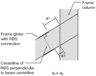
Figure description:
Key Information: Sloped Frame Beam with RBS Connection
- Entities:
- Frame column: Vertical structural element.
- Frame girder: Sloped structural beam intersecting the column.
- Reduced Beam Section (RBS: Connection type indicated by thicker lines on beam flanges.
- RBS Centerline: A dashed line perpendicular to the beam centerline.
- Dimensions/Variables:
- : Distance from column face to the RBS start on the top flange.
- : Distance from column face to the RBS start on the bottom flange.
- Key Detail: . The RBS centerline is oriented perpendicular to the beam flanges rather than parallel to the vertical column centerline to improve performance in sloped configurations.
Fig. C-5.1. Analytical studies (Kim et al., 2010) suggest that a sloped frame beam with RBS centerline perpendicular to beam flanges perform better than if RBS centerline is parallel to column centerline.