Step 2. This step checks that beam flange tensile rupture does not occur before the full plastic moment of the beam is developed at the shear bolts farthest from the column face. The same check is used for the bolted flange plate and cast bolted bracket connections, This check differs from that which appears in AISC Specification
Section F13 (AISC, 2022b) which compares the gross yielding strength of the flange to the net section rupture strength of the flange. The check in Step 2 is predicated on the assumption that there are two bolts in standard holes in the tension flange of the beam, and the approach is substantiated by a study led by Swanson (2016) wherein 18 relevant experiments on bolted flange plate and double-tee connections were identified. In 17 of those experiments, the beam was able to develop at least the full plastic moment strength, and in the 18th experiment, the beam reached approximately of the full plastic moment strength before the beam flange fractured. Equation 13.5-1 predicted that the strength of the beams in all 18 experiments would be governed by gross yielding, whereas the check in AISC Specification Section F13 predicted that gross yielding would govern in only half of the experiments and that net section fracture would govern in the other half. Based on this study, it was determined that the check in AISC Specification Section F13 was overly conservative.
In the event that the check in Step 2 is not satisfied, reinforcement of the beam could be provided. It should be noted, however, that none of the experiments upon which these provisions are based included any reinforcement of the beam flanges at the critical net section. Thus, reinforcing the beam flange is not within the scope of this prequalified connection design procedure.
Step 3. Bolt shear will govern in most cases using typical bolt spacing and end distances. The bearing and tearout strength of the T-stem and beam flange will be checked in Step 18 after additional dimensions of the connection are determined. A simple calculation can be performed at this stage to determine bolt spacing and end distance that will guarantee that shear of the bolt will govern, which will maximize the strength of the shear bolts.
Step 4. Equation 13.5-4 is used to estimate the number of shear bolts that will be required to connect the T-stem to the beam flange. The quantity in the numerator is in place as a preliminary estimate of the moment at the face of column, , which cannot be determined until the number of shear bolts is known.
Step 5. The location of the plastic hinge relative to the column face is determined in this design step. This is based on spacing and end distance of the shear bolts and the setback distance of the end of the beam relative to the column face, which will be much larger than the ½ in. (13 mm) that is typically used for bolted flange plate connections and simple shear connections to allow space for the T-flanges between the end of the beam and column face.
Step 8. The maximum probable flange force is determined by dividing the moment at the column face, , by the distance between centerlines of the stems of the top and bottom T-stubs. Because the thickness of the T-stems has not yet been determined, this distance is estimated as . The expected flange force will be computed using the actual distance between the T-stem in Step 14 after the actual stem thickness is known.
Step 9. The size of the T-stem is determined based on gross yielding and net fracture in tension, and gross yielding or buckling in compression. The gross section of the
T-stem at the first row of shear bolts will be determined by the width of the T-stub and the thickness of the T-stem. The width of the T-stub will be governed by the spacing of the bolts between the T-flange and column flange. As a general rule of thumb, assume that the T-stub will be slightly narrower than the width of the column flange. The lesser of the actual T-stub width and the Whitmore width is used in calculating section properties. If the T-stem is not tapered, the actual width is simply the T-stub width, . If the T-stem is tapered, then the actual width will depend on the geometry of the taper.
The typical gages for beam sections published in the AISC Steel Construction Manual can generally be used for the shear bolts. In some cases, it may be advantageous to use a wider gage as long as edge distance requirements are met, which will increase the Whitmore width of the stem and allow more entering and tightening clearance, but this may lower the block shear strength of the beam flange.
The strength of the T-stem will be backchecked in Step 16 after the section from which the T-stubs are to be cut is selected in Step 12.
Step 10. Equation 13.5-12 provides a lower bound estimate of the required diameter of the tension bolts based on the assumption that there is no prying in the T-flange. Larger bolts may be required depending on the level of prying present in the T-flange and may be desirable to allow a ductile prying mechanism to form in the T-flange (Swanson, 2002).
Step 11. The provisions in this step are based on the prying model developed by Swanson (2002). The strength of the tension bolts and T-flange will be confirmed in Step 17 after the final T-stub dimensions are determined in Step 12. In general, the smallest gage possible for the tension bolts is desirable from a strength point of view; however, larger gages can provide additional ductility in the T-flange at the expense of higher prying forces. The gage of the tension bolts will be governed by the entering and tightening clearances of the tension bolts relative to the beam flange, T-stem, and shear bolts. Care must also be taken to ensure that there is sufficient space between the top and bottom T-stubs for the single-plate shear connection.
The thickness of the T-flange is also a critical parameter and influences the strength of the T-stub greatly. A solution envelope for a typical T-stub is shown in Figure C-13.1 and is the result of plotting the T-stub flange capacity as a function of the flange thickness. The bold line OABC defines the capacity of the flange and tension bolts, and the region below this line represents an adequate design. Segment OA defines the flange mechanism strength and is calculated as using Equation 13.5-43. Segment AB, computed as using Equation 13.5-44, is referred to as a mixed-mode failure because yielding of the T-flange and bolt failure are both expected. Segment BC represents the conventional strength of the bolts without prying and is computed as using Equation 13.5-45. Point A in the chart is generally considered to represent a balanced failure because the full strength of the flange is exhausted at the same time that the bolt forces, including prying, become critical. The flange thickness associated with the point B is often referred to as the critical thickness, , because a
T-stub with a flange thickness greater than that will have negligible prying and will develop the full tensile strength of the bolts.
The initial tension bolt diameter determined in Step 10 using Equation 13.5-12 is based on setting equal to and solving for . The initial flange thickness determined in Step 11 using Equation 13.5-17 corresponds to Segment AB of Figure C-13.1 and is found by setting equal to and solving for . The flange thickness associated with a balanced failure, point A in Figure C-13.1, can be found by setting equal to and solving for , as is shown in Equation 13.5-21. The strength of flanges thinner than the thickness given in Equation 13.5-21 will be governed by a plastic flange mechanism. The critical flange thickness associated with point B in Figure C-13.1 can be found by setting the flange strength for a mixed-mode failure, , equal to the flange strength in the absence of prying, , and solving for , as shown in Equation 13.5-23.
The dimension is estimated in Step 11 as shown in Equation 13.5-14. After the final T-stub dimensions are determined in Step 12, the T-flange and tension bolt strength is back-checked in Step 17, using a different value of as calculated in Equation 13.5-47. When determining the gage of the tension bolts, , keep in mind entering and tightening clearances for the tension bolts, particularly in the side of the T-stem adjacent to the beam where the flange of the beam can interfere with tightening of the tension bolts. Using a smaller tension bolt gage reduces prying forces in the bolts, but if the gage is too small, it may be very challenging, if not impossible, to pretension the tension bolts.
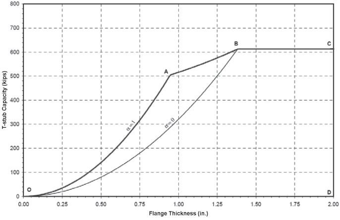
Figure description:
T-stub Capacity (kips vs Flange Thickness (in.
T-stub Capacity vs Flange Thickness
Legend
- α = 1 — color: black; symbol: Thick solid line
- α = 0 — color: black; symbol: Thin solid line
Annotations
- O (text_label - position: (0.00, 0))
- A (text_label - position: (0.95, 505))
- B (text_label - position: (1.37, 615))
- C (text_label - position: (2.00, 615))
- D (text_label - position: (2.00, 0))
- α = 1 (text_label - position: y ≈ 300 on thick curve)
- α = 0 (text_label - position: y ≈ 300 on thin curve)
| Flange Thickness (in.) | T-stub Capacity (kips (α = 1)) | T-stub Capacity (kips (α = 0)) |
|---|---|---|
| 0.00 | 0 | 0 |
| 0.10 | 10 | 5 |
| 0.25 | 45 | 15 |
| 0.50 | 175 | 75 |
| 0.75 | 360 | 175 |
| 0.95 | 505 | 285 |
| 1.00 | 518 | 320 |
| 1.25 | 584 | 510 |
| 1.37 | 615 | 615 |
| 1.50 | 615 | null |
| 1.75 | 615 | null |
| 2.00 | 615 | null |
Notes: The chart illustrates T-stub capacity for two α parameters. Curve α=1 transitions from a parabolic-like curve to a linear segment at point A (0.95, 505 and then to a horizontal plateau at point B (1.37, 615. Curve α=0 follows a single curve from O to point B where it meets α=1.))
Fig. C-13.1. Relationship of T-stub capacity to flange thickness.
Step 12. Select a W-shape that the T-stubs can be cut from. The depth of the W-shape must be sufficiently large to accommodate the distance from the face of the column to the end of the T-stems, which is plus the end distance of the shear bolts in the T-stem. The web thickness and flange thickness of the W-shape must be large enough to accommodate the values of and computed in Steps 9 and 11, respectively. Finally, the flange width of the W-shape must be large enough to accommodate the gage of the tension bolts and the required edge distance.
Step 13. The initial stiffness of the connection is computed based on the stiffness model proposed by Swanson (1999) and is compared to a minimum stiffness of that is required for a FR connection. It is expected that most connections designed on the basis of developing the full plastic moment of the beam will be stiff enough to qualify as FR. Still, this check is required for the double-tee connection.
Step 14. After the final dimensions of the T-stubs and connection are determined, the expected flange force, , is computed based on actual dimensions instead of estimated dimensions.
Step 15. After the expected flange force, , has been determined and the actual dimensions of the connection are known, the strength of the shear bolts is checked to ensure that they are adequate.
Step 16. After the expected flange force, , has been determined and the actual dimensions of the connection are known, the strength of the T-stem is checked to ensure that it is adequate.
Step 17. After the expected flange force, , has been determined and the actual dimensions of the connection are known, the strength of the T-flange and tension bolts is checked to ensure that they are adequate. Shear and tension interaction in the tension bolts need not be considered. Because the shear plate will undoubtedly be much stiffer with respect to vertical forces than the T-stem, it is safely assumed that the web bolts carry all of the beam shear force to the column while the tension bolts carry only tension resulting from the beam moment. This can be demonstrated by considering the ratio of the stiffness of the shear plate to the stiffness of the T-stems on the top and bottom flanges of the beam.
If it is assumed that , and , then this ratio reduces to 25 indicating that the shear connection is 25 times stiffer than the flange connections with respect to resisting vertical forces.
Step 18. Bearing and tearout of the shear bolts relative to the T-stem and beam flange is checked consistent with AISG Specification Section J3.11 using actual dimensions and the expected flange force, .
Step 19. Block shear of the T-stem and beam flange should be checked in a manner consistent with AISC Specification Section J4.3. For the purpose of this design, the block shear failure is considered a ductile failure mode.
The “alternate block shear” mechanism illustrated in Figure 13.7 need not be checked. For this failure mechanism to form, a net rupture of the beam flange must occur, and this is precluded by the check in Step 2. In numerous documented tests of double-tee and bolted flange plate connections, this alternative block shear mechanism has not been observed.
Step 21. Because of the large setback required, the shear connection will most likely need to be designed as an “extended” single-plate shear connection. Most importantly, the length of the shear connection, , should be determined so as to fit between the flanges of the T-stubs allowing ample clearance.
Consistent with AISC Specification Section J4.3, block shear of the beam web should be checked for the failure path shown in Figure C-13.2. For the purpose of this design, the block shear failure shall be considered a ductile failure mode.
Step 22. The strength of the column flange adjacent to the T-stub is checked in this step. A yield line analysis is the basis for the strength in Equations 13.5-53 through 13.5-59. The yield-line pattern is shown in Figure 13.8, wherein it is assumed that the top T-stub is in tension. With the requirement that both T-stubs be identical, checking only one location is satisfactory.
Note that the yield-line pattern shown in Figure 13.8 is applicable to both the cases of T-stubs with eight tension bolts or four tension bolts. In the case where eight tension bolts are used, the yield pattern is defined by the inner four bolts and the associated gage, , shown in the figure.
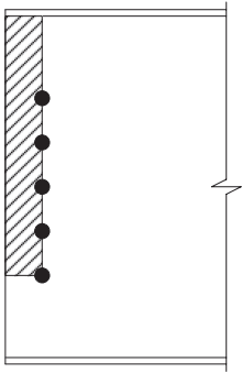
Figure description:
Key Information:
- Subject: Block shear failure mode in a beam web (Fig. C-13.2.
- Entities:
- Beam Web: The main structural vertical plate.
- Bolts: Five circular black dots representing a single vertical row of fasteners.
- Failure Zone: A rectangular cross-hatched area indicating the material section expected to tear out.
- Orientation: The shaded failure region extends from the top edge of the beam web down to the bottom-most bolt and out to the left vertical edge.
Fig. C-13.2. Block shear failure mode for the beam web.
Step 23. In checking the column for web local yielding and web local crippling consistent with AISC Specification Sections J10.2 and J10.3, respectively, the bearing length, , can be taken as , where is the dimension of the T-stub and is the T-stub stem thickness. Given the requirement for continuity plates, however, web local yielding and web local buckling are not expected to control.