12.8.1 Beam Coping
Beams shall be coped in accordance with Figure 12.3(a).
12.8.2 Yield-Links
Yield-Links shall conform to the requirements of Figures 12.2 and 12.3 and shall be fabricated using ASTM A572/A572M Grade 50 (Grade 345) material or rolled
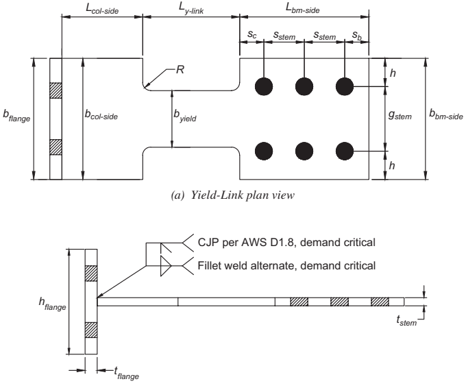
Figure description:
Entity: Yield-Link structural connector
Key Components & Views:
- (a Plan View: Shows horizontal geometry, including column-side plate (, reduced yield section (, and beam-side plate ( with six bolt holes.
- (b Elevation View: Shows vertical profile, including flange height (, flange thickness (, and stem thickness (.
Key Dimensions:
- Widths: , , (narrowest part, and .
- Spacing: Bolt hole layout defined by (horizontal and (vertical.
- Radius (: Transition curve into the yield section.
Weld Specifications:
- CJP (Complete Joint Penetration: per AWS D1.8, demand critical.
- Fillet weld alternate: demand critical.
(b) Yield-Link elevation view
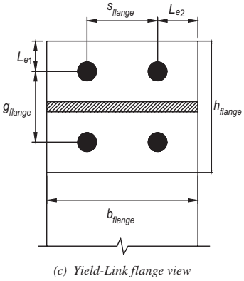
Figure description:
Yield-Link Flange View (Fig. 12.2c
This diagram details the geometric parameters of a Yield-Link flange:
- : Total width of the flange plate.
- : Total height of the flange plate.
- : Horizontal center-to-center spacing between bolt holes.
- : Vertical center-to-center spacing between bolt holes.
- : Vertical edge distance from the top edge to the center of the upper bolt holes.
- : Horizontal edge distance from the side edge to the center of the outer bolt holes.
- Bolt Holes: Four circular holes arranged in a rectangular pattern.
- Central Feature: A horizontal hatched area dividing the upper and lower bolt pairs.
Fig. 12.2. Yield-Link geometries.
sections conforming to the ASTM A992/A992M or ASTM A913/A913M Grade 50 (Grade 345) specification. Each pair of Yield-Link stems at a connection shall be cut from the same heat of material. Minimum Yield-Link stem thickness shall be ½ in. (13 mm), and maximum Yield-Link stem thickness shall be 1 in. (25 mm), with a thickness tolerance in accordance with ASTM A6/A6M. Yield-Link flange edge distances, and , shall conform to AISC Specification Tables J3.4 or J3.4M.
12.8.3 Shear-Plate Connection Bolts
Shear-plate connection bolts shall be designed to resist the required axial and shear forces; see Figure 12.1 and Section 12.9, Step 15.
12.8.4 Shear-Plate Shear Connection Welds
The single-shear plate connection shall be welded to the column flange or end plate using double-sided fillet welds, PJP groove welds, or CJP groove welds, sized in accordance with Section 12.9, Step 15.4.
12.8.5 Bolt Hole Requirements
- (1) Standard bolt holes shall be provided in the beam flanges and beam webs. Oversized holes or vertical slots are permitted in the column flanges with T-stub Yield-Links. Standard size bolt holes shall be used in the end plate and column flanges when using end-plate Yield-Links.
- (2) The central bolt hole in the shear plate shall be a standard hole. Remaining bolt holes for bolts resisting shear and axial forces shall be slotted to accommodate a connection rotation of at least 0.07 rad.
12.8.6 Buckling Restraint Assembly
The buckling restraint assembly consists of the buckling restraint plate, the buckling restraint spacer plate, and the buckling restraint bolts and shall conform to the requirements of Figure 12.3. Design of the buckling restraint plate assembly shall be in accordance with Section 12.9, Step 10. The buckling restraint plate shall be a minimum of 7/8 in. (22 mm) thick, with a specified minimum yield stress (345 MPa). The buckling restraint plate shall extend from the centerline of the vertical shear bolt holes to the end of the cut region of the Yield-Link plate. The buckling restraint spacer plate shall have the same thickness as the Yield-Link stem, with a specified minimum yield stress . Buckling restraint bolts shall have a minimum diameter of 5/8 in. (16 mm).
12.8.7 Shims
The use of finger shims at the T-stub or end-plate Yield-Link flange-to-column flange is permitted, subject to the limitations of the RCSC Specification.