Welding of the beam to the collar flange shall conform to the following limitations:
- (1) Weld access holes are not permitted. Welding access to top and bottom flanges shall be made available by rotating the beam to allow a CJP weld in the flat position (position 1G per AWS D1.1/D1.1M).
- (2) The beam flange-to-collar flange weld shall be made with a CJP groove weld within the weld prep area of the collar flange. Reinforcing 5/16 in. (8 mm) fillet welds shall be placed on the back side of the CJP groove welds. The CJP flange weld shall conform to the requirements for demand critical welds in the AISCE Seismic Provisions and AWS D1.8/D1.8M, and to the requirements of AWS D1.1/D1.1M.
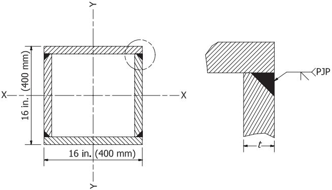
Figure description:
Entity: Built-up Box Column
- Dimensions: 16 in. x 16 in. (400 mm x 400 mm square section.
- Structure: Composed of two flange plates and two web plates joined at corners.
- Axes: Defined by X-X and Y-Y centerlines.
Detail: Flange-to-Web Connection
- Connection Type: Partial Joint Penetration (PJP groove weld.
- Weld Symbol: PJP indication with a flare-bevel or V-groove configuration.
- Material Thickness: Web plate thickness denoted as .
- Configuration: The flange plate overlaps the web plate; the weld is placed in the corner interface.
Fig. 10.5. Built-up box column flange-to-web connection detail.
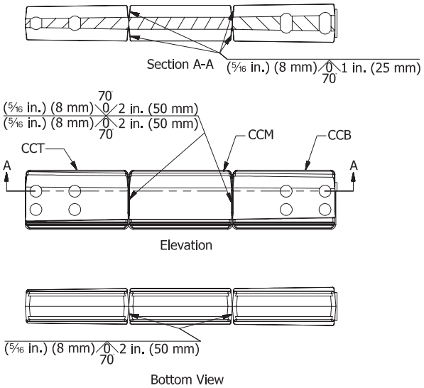
Figure description:
Technical drawing: Fig. 10.6. Collar corner assembly welding.
Key Components:
- CCT: Collar Corner Top
- CCM: Collar Corner Middle
- CCB: Collar Corner Bottom
Views and Welding Specifications:
- Elevation View: Shows three connected sections with weld callouts at the vertical joints.
- Weld type: Double-sided fillet/flare-bevel welds.
- Size: 5/16 in. (8 mm.
- Length: 2 in. (50 mm.
- Angle: 70°.
- Section A-A (Top-down cutaway:
- Weld type: Single-sided fillet/flare-bevel welds at interior joints.
- Size: 5/16 in. (8 mm.
- Length: 1 in. (25 mm.
- Angle: 70°.
- Bottom View:
- Weld type: Fillet/flare-bevel welds at bottom joints.
- Size: 5/16 in. (8 mm.
- Length: 2 in. (50 mm.
- Angle: 70°.
Fig. 10.6. Collar corner assembly welding.
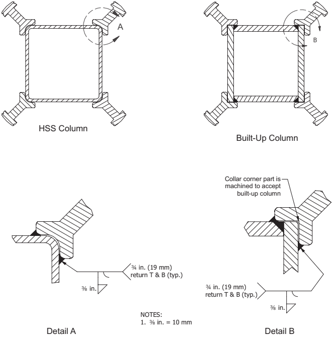
Figure description:
Subject: Collar corner assembly-to-column weld (plan view.
Key Entities and Specifications:
- HSS Column: Assembly attached to the rounded corners of a Hollow Structural Section.
- Built-Up Column: Assembly attached to sharp-cornered fabricated columns; collar corner parts are machined to accept the specific geometry.
- Detail A (HSS Column:
- 3/8 in. (10 mm fillet weld.
- 3/4 in. (19 mm return at top and bottom (typ..
- Detail B (Built-Up Column:
- Machined collar corner for flush fit.
- 3/8 in. (10 mm fillet welds on both sides of the corner engagement.
- 3/4 in. (19 mm return at top and bottom (typ..
- Notes: Conversion provided as 3/8 in. = 10 mm.
Fig. 10.7. Collar corner assembly-to-column weld, plan view.
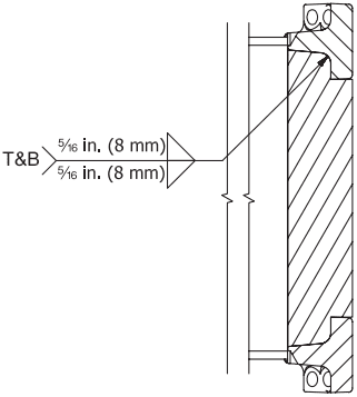
Figure description:
Key Information:
- Subject: Elevation view of collar web extension-to-collar flange welds.
- Weld Specifications:
- Type: Fillet welds on both sides of the joint.
- Size: 5/16 in. (8 mm for both top and bottom (T&B.
- Components: Cross-hatched flange components connected to a vertical web extension, with the weld location indicated at the interior junction.
Fig. 10.8. Collar web extension-to-collar flange welds, elevation.
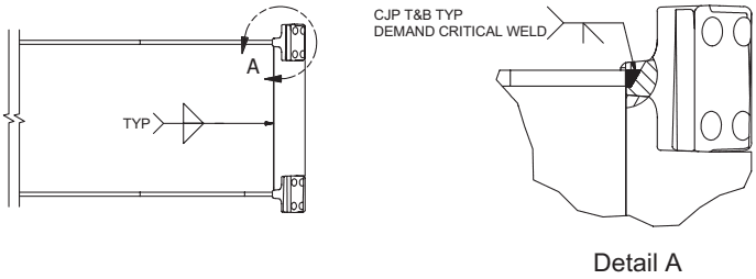
Figure description:
Key Information:
- Components: Beam, collar flange assembly, and collar web extension.
- Weld Specification (Detail A: Complete Joint Penetration (CJP welds at top and bottom (T&B positions.
- Weld Classification: Designated as "Demand Critical Weld."
- Elevation Details:
- Fig. 10.8: Shows collar web extension-to-collar flange welds.
- Fig. 10.9: Shows collar flange assembly-to-beam welds.
- Typical Weld Symbol: A typical (TYP fillet weld is indicated for vertical web connections.
Fig. 10.9. Collar flange assembly-to-beam welds, elevation.