11.3.1 Beam Limitations
Beams shall satisfy the following limitations:
- (1) Beams shall be rolled wide-flange, HSS, or built-up I-shaped beams conforming to the requirements of Section 2.3. Beam flange thickness shall be limited to a maximum of 3.25 in. (81 mm).
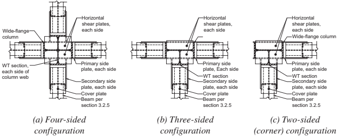
Figure description:
Subject: SidePlate biaxial field-welded connection with built-up flanged cruciform column plan views.
Configurations:
- (a Four-sided configuration: Central column with four orthogonal beam connections.
- (b Three-sided configuration: Central column with three beam connections in a T-shape.
- (c Two-sided (corner configuration: Central column with two orthogonal beam connections in an L-shape.
Key Components:
- Columns: Built-up flanged cruciform using a wide-flange section and WT sections attached to each side of the column web.
- Plates:
- Primary side plates (each side
- Secondary side plates (each side
- Horizontal shear plates (each side
- Cover plates
- Beams: Connected to the column assembly via the side and shear plate systems.
Fig. 11.5. SidePlate biaxial field-welded connection with built-up flanged cruciform column plan views.
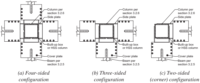
Figure description:
The image displays three plan view configurations for SidePlate biaxial field-bolted connections with built-up box or HSS columns:
-
Key Components:
- Column: Built-up box or HSS column.
- Side plate: Vertical plates flanking the connection.
- Cover plate: Bolted plates connecting beams to the side plates/column.
- Beam: Horizontal structural members attached to the assembly.
-
Configurations:
- (a Four-sided configuration: Beams connected to all four sides of the column.
- (b Three-sided configuration: Beams connected to three sides of the column.
- (c Two-sided (corner configuration: Beams connected to two adjacent sides of the column.
Fig. 11.6. SidePlate biaxial field-bolted connection with built-up box/HSS columns plan views.
- (2) Rolled wide-flange beam depths shall be limited to W40 (W1000) and W44 (W1100) for the field-welded and field-bolted connections, respectively. The depth of built-up wide-flange beams shall not exceed the depth permitted for rolled wide-flange beams.
- (3) Beam depths shall be limited as follows for HSS shapes:
- (a) For SMF systems, HSS14 (HSS 356) or smaller.
- (b) For IMF systems, HSS16 (HSS 406) or smaller.
- (4) Rolled and built-up wide-flange beam weight shall be limited to 302 lb/ft (450 kg/m) and 529 lb/ft (790 kg/m) for the field-welded and field-bolted connections, respectively. Beam flange area of the field-bolted connection shall be limited to a maximum of 48 in.² (30 000 mm²).
- (5) The ratio of the hinge-to-hinge span of the beam, , to beam depth, , shall be limited as follows:
- (a) For SMF systems, is limited to the following:
- (i) 6 or greater with rectangular shaped cover plates.
- (ii) 4.5 or greater with U-shaped cover plates for field-welded connections.
- (iii) 4.0 or greater with U-shaped cover plates for field-bolted connections.
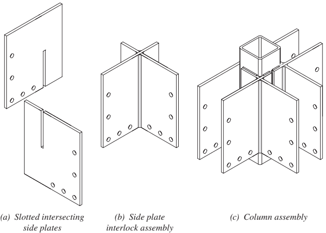
Figure description:
SidePlate Built-up Box/HSS Biaxial Configuration
- (a Slotted Intersecting Side Plates: Individual steel plates featuring vertical slots and pre-drilled bolt holes for structural connections.
- (b Side Plate Interlock Assembly: Two side plates joined orthogonally by sliding their respective slots into one another to form a cross-shaped core.
- (c Column Assembly: The final configuration integrating the interlocked side plates around a central HSS (Hollow Structural Section or built-up box column, providing biaxial connection points for beams.
Fig. 11.7. SidePlate built-up box/HSS biaxial configuration.
(b) For IMF systems, is limited to 3 or greater.
The hinge-to-hinge span of the beam, , is the distance between the locations of plastic hinge formation at each moment-connected end of that beam. The location of the plastic hinge shall be taken as one-third of the beam depth, , for the field-welded connection and one-sixth of the beam depth, , for the field-bolted connection, away from the end of the side-plate extension, as shown in Figure 11.9. Thus,
where
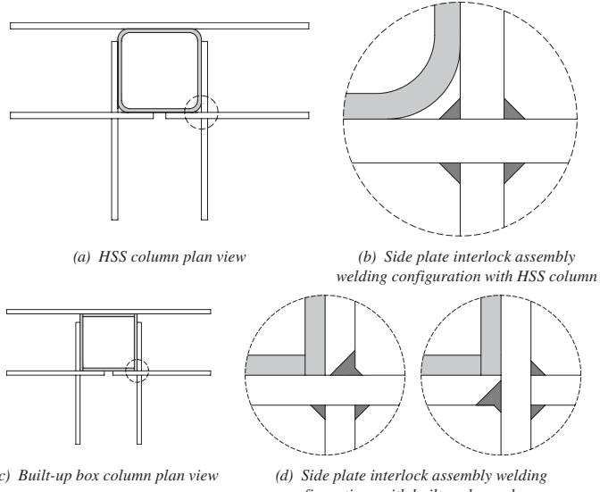
Figure description:
The image displays structural engineering diagrams for side plate interlock assembly welding configurations.
Key Entities and Details:
- HSS Column: Hollow Structural Section column shown in plan view (a and detail (b.
- Built-up Box Column: Square column fabricated from plates, shown in plan view (c and detail (d.
- Side Plates: External plates arranged around the column for connection.
- Welding Configurations:
- Detail (b: Shows fillet welds at the junction of the HSS column and interlocking side plates.
- Detail (d: Illustrates two variations of fillet weld placement for built-up box columns at the plate interlock points.
- Context: The diagrams focus on the interlock assembly where side plates meet at the corners of either HSS or built-up box columns in a moment frame configuration.
(d) Side plate interlock assembly welding configurations with built-up box column
Fig. 11.8. Biaxial side plate interlock assembly welding options.
User Note: The 0.33d and 0.165d constants represent the distance of the plastic hinge from the end of the side plate extension. A represents the typical extension of the side plates from the face of column flange.
- (6) Width-to-thickness ratios for beam flanges and webs shall conform to the limits of the AISC Seismic Provisions.
- (7) Lateral bracing of wide-flange beams shall be provided in conformance with the AISC Seismic Provisions. Lateral bracing of HSS beams shall be provided in conformance with AISC Specification Appendix 1, Section 1.3.2c, taking in AISC Specification Equation A-1-7. For either wide-flange or HSS beams, the segment of the beam connected to the side plates shall be considered to be braced. Supplemental top and bottom beam flange bracing at the expected hinge is not required.
- (8) The protected zone in the beam for the field-welded and field-bolted connec- tions shall consist of the portion of the beam as shown in Figures 11.10 and 11.11, respectively.
11.3.2 Column Limitations
Columns shall satisfy the following limitations:
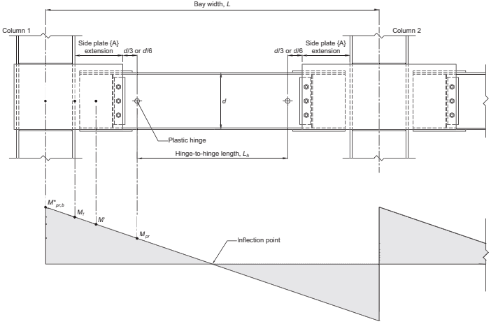
Figure description:
Structural Geometry and Moment Diagram Geometrical and Moment Analysis of SidePlate Connection
Moment Diagram and Structural Locations
Annotations
- Plastic hinge (text_label - position: Located at d/3 or d/6 from the side plate extension)
- Inflection point (text_label - position: Midpoint of the beam where moment is zero)
- Bay width, L (text_label - position: Distance between centerlines of Column 1 and Column 2)
- Hinge-to-hinge length, Lh (text_label - position: Distance between the two symmetric plastic hinges)
- Side plate {A} extension (text_label - position: Horizontal distance from column face to the end of the side plate)
- d/3 or d/6 (text_label - position: Standardized distance from plate extension to plastic hinge)
- d (text_label - position: Beam depth)
| Location Along Beam | Moment Identifier |
|---|---|
| Centerline of Column 1 | M*pr,b |
| Face of Column 1 | Mf |
| End of Side Plate {A} Extension | M' |
| Plastic Hinge Location | Mpr |
| Beam Mid-span | Inflection point (Zero Moment) |
Notes: The figure illustrates the geometric parameters and corresponding bending moment distribution for a SidePlate beam-to-column connection. The moment diagram is shown as an anti-symmetric distribution typical of lateral load conditions.
Fig. 11.9. Plastic hinge location and hinge-to-hinge length.
- (1) Columns shall be any of the shapes permitted in Section 2.3. Flange and web plates of built-up box columns shall continuously be connected by fillet welds or PJP groove welds along the length of the column.
- (2) HSS column shapes shall conform to ASTM A500/A500M or A1085/A1085M.
- (3) The beam shall be connected to the side plates that are connected to the flange tips of the wide-flange column or corners/sides of HSS or box columns.
- (4) Rolled shape column depth shall be limited to W44 (W1100). The depth of built-up wide-flange columns shall not exceed that for rolled shapes. Flanged cruciform columns shall not have a width or depth greater than the depth allowed for rolled shapes. Built-up box columns shall not have a width exceeding 33 in. (840 mm).
- (5) There is no limit on column weight per foot. (6) There are no additional requirements for colu (7) Width-to-thickness ratios for the flanges and
- (6) There are no additional requirements for column flange thickness.
- Width-to-thickness ratios for the flanges and webs of columns shall conform to the requirements of the AISC Seismic Provisions.
- (8) Lateral bracing of columns in accordance with AISC Seismic Provisions Section E3.4c1 is not a requirement if the beam is braced at the top beam flange (e.g., with a deck or slab), otherwise, lateral bracing of columns shall conform to the requirements of the AISC Seismic Provisions.
11.3.3 Connection Limitations
The connection shall satisfy the following limitations.
- (1) Material used for plate elements shall comply with the following:
- (a) For the side plate interlock assembly shown in Figure 11.7 that utilizes plates greater than 2¼ in. (57 mm) in thickness, the intersecting plates shall be fabricated from structural steel that complies with ASTM A709/A709M Grade 50T zone 2 (Grade 345T) or normalized ASTM A572/A572M Grade 50 (Grade 345).
- (b) All other connection plates, which consist of side plates, cover plates, horizontal shear plates, and vertical shear elements (if applicable) shall be fabricated from structural steel that complies with ASTM A572/A572M Grade 50 (Grade 345).
Exception: The vertical shear element as defined in Section 11.6 may be fabricated using ASTM A36/A36M material.
-
(2) The extension of the side plates beyond the face of the column shall be within the range of 0.65d to 1.0d for the field-welded connection and 0.65d to 1.7d for the field-bolted connection, where d is the nominal depth of the beam.
-
(3) The protected zone of the connection in the side plates shall consist of a portion of each side plate that is 6 in. (150 mm) high and starts at the inside face of the flange of a wide-flange or HSS column and ends either at the end of the gap (field-welded connection) or the edge of the first bolt hole (field-bolted connection) as shown in Figures 11.10 and 11.11.