The SidePlate® moment connection utilizes interconnecting plates to connect beams to columns. The connection features a physical separation, or gap, between the face of the column flange and the end of the beam(s). Both field-welded and field-bolted options are available. Beams may be either rolled or built-up wide-flange sections or hollow structural sections (HSS). Columns may be either rolled or built-up wide-flange, built-up box, boxed I-shaped, or HSS sections. Built-up flanged cruciform sections consisting of rolled shapes or built up from plates may also be used as columns for biaxial configurations. Figures 11.1, 11.2, and 11.3 show the various field-welded and field-bolted uniaxial connection configurations. The field-bolted option is available in three configurations, referred to as configuration A (standard), configuration B (narrow), and configuration C (tuck) as shown in Figure 11.3.
In the field-welded connection, top and bottom beam flange cover plates (rectangular or U-shaped) are used at the end(s) of the beam, as applicable, which also serve to bridge any difference between flange widths of the beam(s) and of the column. The connection of the beam to the column is accomplished with parallel full-depth side plates that sandwich and connect the beam(s) and the column together. In the field-bolted connection, beam flanges are connected to the side plates with either a cover plate or a pair of angles and high-strength pretensioned bolts as shown in Figures 11.2 and 11.3. Column horizontal shear plates and beam vertical shear elements (as applicable) are attached to the wide-flange column and beam webs, respectively.
Figure 11.4 shows the connection geometry and major connection components for uniaxial field-welded configurations.
Figure 11.5 shows the connection geometry and major connection components for biaxial field-welded configurations, which permits connecting up to four beams to a column. Figure 11.6 shows the analogous field-bolted biaxial connection with built-up box or HSS columns. Built-up box and HSS columns may be filled with concrete. All field-bolted beam configurations as shown in Figure 11.3 and all field-welded configurations as shown in Figure 11.4 are permitted in biaxial applications.
Figure 11.7 shows the SidePlate built-up box/HSS biaxial configuration. Figure 11.7(b) shows the assembly of the two intersecting side plates that are attached to the column to receive the beams as shown in Figure 11.7(c). Each side plate is slotted to accommodate the other orthogonal side plate as shown in Figure 11.7(a). The configuration shown in Figure 11.7(b) will be referred to as the side plate interlock assembly herein.
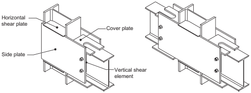
Figure description:
Key Entities and Information:
- System: SidePlate steel connection system for wide-flange beam and column construction.
- Configurations shown:
- One-sided connection (Left: A single wide-flange beam attached to a column.
- Two-sided/Continuous connection (Right: Beams attached to opposite sides of a column.
- Key Components:
- Side Plate: Large vertical plate that spans the column-beam interface.
- Horizontal Shear Plate: Plate positioned horizontally at the beam flange level.
- Vertical Shear Element: Component connecting the beam web to the side plate.
- Cover Plate: Horizontal plate reinforcing the top/bottom of the connection assembly.
- Mechanical Features: Uses a "side plate interlock assembly" where plates are slotted to accommodate orthogonal members in biaxial configurations.
(a) One-sided wide-flange beam and column construction
(b) Two-sided wide-flange beam and column construction
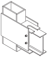
Figure description:
Structural Steel Connection Detail
- Connection Type: Wide-flange beam to HSS or built-up box column.
- Key Components:
- Column: Rectangular HSS or built-up box section.
- Beam: Wide-flange (I-beam section.
- Side Plate: Bolted external plate reinforcing the connection.
- Horizontal Plates: Internal diaphragm or continuity plates, one featuring a U-shaped cutout for beam integration.
- Fasteners: Two visible bolts/nuts securing the side plate to the beam-column interface.
(c) Wide-flange beam to either HSS or built-up box column
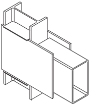
Figure description:
Key Information:
- Structural Connection: Represents an HSS (Hollow Structural Section beam-to-column connection.
- Key Entities:
- Wide-flange column: The vertical structural member.
- Rectangular HSS beam: The horizontal structural member.
- Side plates: Large vertical plates connecting the HSS beam sides to the column flanges.
- Geometric Detail: The width of the HSS beam matches the flange width of the wide-flange column.
- Context: Illustrates a connection type (d where an HSS beam without cover plates is joined to a wide-flange column of equal width.
(d) HSS beam without cover plates to wide-flange column with the same flange width
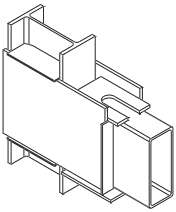
Figure description:
Key Information:
- Entities: Rectangular HSS (Hollow Structural Section beam and a wide-flange (I-shape steel column.
- Connection Type: Rigid moment connection.
- Details:
- Horizontal diaphragm plates are positioned at the top and bottom levels of the HSS beam.
- The top plate features a slot to fit around the column web, facilitating a continuous load path across the column.
- The plates are welded to both the HSS beam and the column flanges/web to transfer moment and shear forces.
(e) HSS beam to wide-flange column
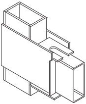
Figure description:
Subject: Structural steel connection diagram for an HSS beam to an HSS or built-up box column.
Key Entities:
- Vertical Column: Rectangular Hollow Structural Section (HSS or built-up box column.
- Horizontal Beam: Rectangular HSS beam.
- Diaphragm Plates: Horizontal plates welded to the exterior of the column that extend to the top and bottom of the beam.
- Top Plate Detail: Features a U-shaped cutout (slot to fit around the vertical column profile.
- Side Plates: Vertical plates connecting the horizontal diaphragm plates along the sides of the beam connection.
(f) HSS beam to either HSS or built-up box column
Fig. 11.1. Assembled SidePlate uniaxial field-welded configurations.
Two different details may be used for constructing the side plate interlock assembly depending on the type of the column. Figure 11.8(a) shows the plan view of a typical SidePlate biaxial configuration with an HSS column where the side plates are connected with four fillet welds as shown in Figure 11.8(b). Figure 11.8(c) shows a typical SidePlate biaxial configuration with a built-up box column where the side plates are connected with a combination of fillet and PJP groove welds as shown in Figure 11.8(d). The latter detail with PJP groove welds may also be used with HSS columns.
User Note: The side plate interlock assembly may be preassembled prior to attachment to the HSS or built-up box columns. The side plates of the interlock assembly with PJP groove welds shown in Figure 11.8(d) may alternatively be attached to the column one at a time while turning the column around its longitudinal axis.
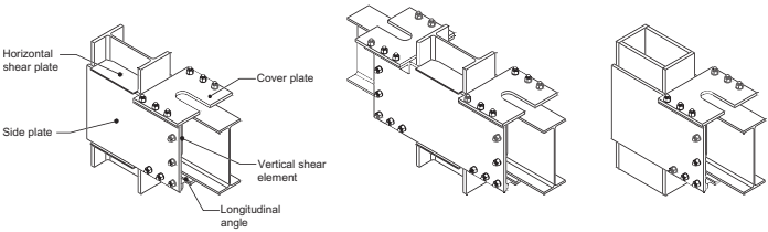
Figure description:
The image displays structural steel connection diagrams for beams and columns.
Key Components:
- Side plate: Large vertical plate connecting the beam assembly to the column.
- Cover plate: Bolted horizontal plate connecting the top flange of the beam.
- Horizontal shear plate: Top horizontal element bridging the side plates across the column.
- Vertical shear element: Vertical connection piece between the beam web and side plate.
- Longitudinal angle: Support angle at the bottom of the beam-to-plate connection.
Connection Configurations:
- Left: One-sided connection using wide-flange (I-beam sections for both beam and column.
- Center: Two-sided connection with wide-flange beams on both sides of a wide-flange column.
- Right: One-sided wide-flange beam connection to a rectangular HSS (Hollow Structural Section or box column.
(a) One-sided wide-flange beam and column construction
(b) Two-sided wide-flange beam and column construction
(c) Wide-flange beam to either HSS or built-up box column
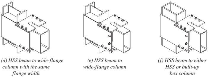
Figure description:
Fig. 11.2 Assembled Side Plate uniaxial field-bolted standard configurations (Configuration A
- (d HSS beam to wide-flange column: Specific configuration where the beam width matches the column flange width.
- (e HSS beam to wide-flange column: General configuration for an HSS beam joining a wide-flange column.
- (f HSS beam to HSS or built-up box column: Configuration for joining an HSS beam to rectangular column sections.
- Key components: Hollow Structural Section (HSS beams, wide-flange/box columns, side plates, and field bolts.
Fig. 11.2. Assembled SidePlate uniaxial field-bolted standard configurations (configuration A).
The SidePlate moment connection is proportioned to develop the probable maximum moment capacity of the connected beam. Plastic hinge formation is intended to occur primarily in the beam beyond the end of the side plates away from the column face, with limited yielding occurring in some of the connection elements.
User Note: Moment frames that utilize the SidePlate connection can be constructed using one of three methods: the full-length beam erection method (SidePlate FRAME configuration), the link-beam erection method (SidePlate Original configuration), and the fully shop prefabricated method. These methods are described in the Commentary.