Double-tee connections utilize T-stub components that are bolted to both the column flange and the beam flanges using high-strength bolts. Either four bolts or eight bolts attach the T-stub components to the column flanges. The top and bottom T-stubs shall be identical. T-stubs shall be cut from rolled sections. The beam web is connected to the column with a bolted single-plate shear connection. A detail for this connection is shown in Figure 13.1. Yielding and hinge formation are intended to occur in the beam near the ends of the stems of the T-stubs. Figures 13.2 through 13.6 provide details regarding the dimensioning notation used in this chapter.
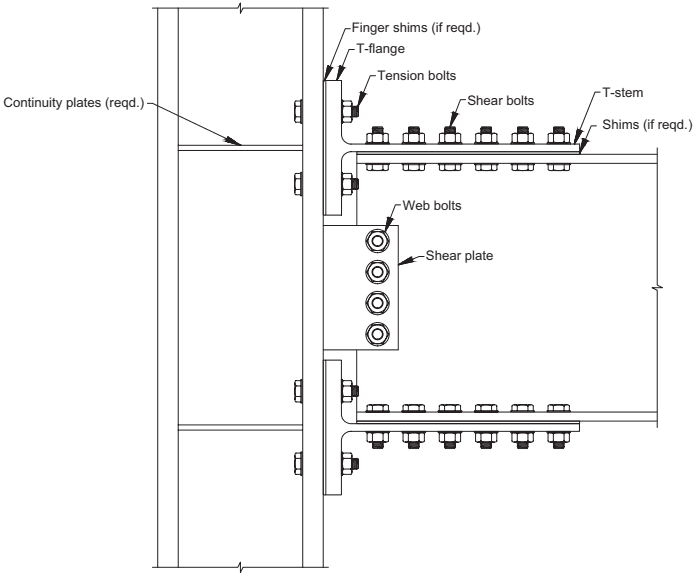
Figure description:
Figure 13.1: Typical double-tee connection
Key Components and Features:
- Structural Members: Vertical column connected to a horizontal beam using a double-tee configuration.
- T-Stub Components: Top and bottom T-sections consisting of a T-flange (bolted to the column and a T-stem (bolted to the beam flange.))
- Bolting System:
- Tension bolts: Connect T-flanges to the column flange.
- Shear bolts: Connect T-stems to the beam flanges.
- Web bolts: Secure the beam web to the column via a shear plate.
- Support Plates: Continuity plates installed within the column's web area aligned with the T-flanges.
- Adjustments: Finger shims and standard shims are indicated for use between connecting surfaces if required.
Fig. 13.1. Typical double-tee connection.
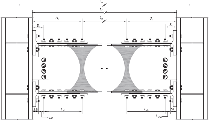
Figure description:
The image illustrates beam dimensions for double-tee structural connections.
Key Dimensions:
- : Overall length between column centers.
- : Clear span between column faces.
- : Distance between the centers of the plastic hinge regions.
- : Distance from the column face to the center of the plastic hinge.
- : Distance from the column face to the first row of bolts.
- : Setback distance from the column face to the end of the beam.
- : Length of the vertical bolt group.
- : Edge distance for horizontal bolts.
Key Components:
- Double-Tee Connectors: Bolted to the beam flanges and column faces.
- Shear Tab: Bolted to the beam web at each end.
- Plastic Hinges: Shaded areas located in the beam web and flanges near the connections.
- Structural Columns: I-beam sections at both ends supporting the central beam.
Fig. 13.2. Beam dimensions for double-tee connections. Shaded regions represent plastic hinges.
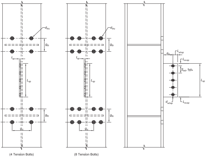
Figure description:
Key Information: Column and Shear Plate Dimensions (Fig. 13.3
The image details structural dimensions for double-tee connections in two configurations: 4 Tension Bolts and 8 Tension Bolts.
Key Entities and Parameters:
- Column Tension Bolt Layout:
- : Diameter of tension bolt holes in the column.
- : Vertical gauge distance between tension bolt rows.
- : Horizontal gauge distance between inner columns of bolts.
- Shear Plate Dimensions:
- : Total height/length of the shear plate.
- : Thickness of the shear plate.
- : Horizontal edge distance from the bolt centerline to the plate edge.
- : Vertical edge distance from the top/bottom bolts to the plate edge.
- : Horizontal distance from the column face to the centerline of the shear plate bolts.
- Web Bolt Layout:
- : Diameter of web bolt holes in the shear plate.
- : Typical vertical spacing between bolts in the shear plate.
Fig. 13.3. Column and shear plate dimensions for double-tee connections.