The provisions of this section require the introduction of several new variables. The quantity represents both an axial displacement and a rotational quantity. Both quantities are determined by examining the profile of the building at the design earthquake displacement, , and extracting joint lateral and rotational deformation demands.
Determining the maximum rotation imposed on the braces used in the building may require significant effort. The engineer may prefer to select a reasonable value (in other words, story drift), which can be simply demonstrated to be conservative for each brace type, and is expected to be within the performance envelope of the braces selected for use on the project.
Two types of testing are referred to in this section. The first type is subassemblage testing, described in Section K3.2, an example of which is illustrated in Figure C-K3.1.
The second type of testing, described in Section K3.3 as brace specimen testing, is permitted to be uniaxial testing.
K3.1 Scope
The development of the testing requirements in the Provisions was motivated by the relatively small amount of test data on buckling-restrained braced frames (BRBF) available to structural engineers. In addition, relatively little data on the response of BRBF to severe ground motion is available. BRB successfully withstood design-level demands during the 2011 Tohoku earthquake, as well as considerable shaking in the 2017 Puebla earthquake near Mexico City and the 2020 Aegean Sea earthquake.
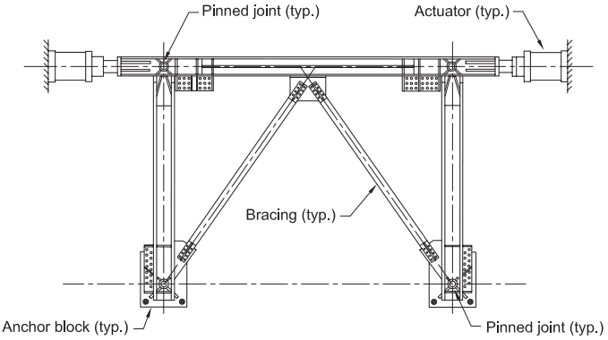
Figure description:
Fig. C-K3.1. Example of test subassemblage
Key Components:
- Actuators: Positioned horizontally at both top ends to apply lateral loads.
- Pinned joints: Located at the beam-to-column connections and at the base of the columns.
- Bracing: Diagonal buckling-restrained braces connected to the beam and column joints.
- Anchor blocks: Base supports securing the vertical columns to the foundation.
- Structural Frame: Composed of a horizontal beam supported by two vertical columns forming a single-bay subassemblage.
Fig. C-K3.1. Example of test subassemblage.
Nevertheless, the seismic performance of these systems is relatively unknown compared to more conventional steel-framed structures.
The behavior of a BRBF differs markedly from conventional braced frames and other structural steel seismic force-resisting systems. Various factors affecting brace performance under earthquake loading are not well understood, and the requirement for testing is intended to provide assurance that the braces will perform as required and also to enhance the overall state of knowledge of these systems.
It is recognized that testing of brace specimens and subassemblages can be costly and time-consuming. Consequently, this section has been written with the intent of providing the simplest testing requirements possible, while still providing reasonable assurance that prototype BRBF based on brace specimens and subassemblages tested in accordance with these provisions will perform satisfactorily in an actual earthquake.
It is not intended that the Provisions drive project-specific tests on a routine basis for building construction projects. In most cases, tests reported in the literature or supplied by the brace manufacturer can be used to demonstrate that a brace and sub- assemblage configuration satisfies the strength and inelastic rotation requirements of these Provisions. Such tests, however, should satisfy the requirements of this section.
The provisions of this section have been written allowing submission of data on previous testing, based on similar conditions. As the body of test data for each brace type grows, the need for additional testing is expected to diminish. The Provisions allow for manufacturer-designed braces, through the use of a documented design methodology.
Most testing programs developed for primarily axial-load-carrying components focus largely on uniaxial testing. However, the Provisions are intended to direct the primary focus of the program toward testing of a subassemblage that imposes combined axial and rotational deformations on the brace specimen. This reflects the view that the ability of the brace to accommodate the necessary rotational deformations cannot be reliably predicted by analytical means alone. Subassemblage test requirements are discussed more completely in Commentary Section K3.2.
A considerable number of uniaxial tests have been performed on some brace systems, and the engineer is encouraged, wherever possible, to submit previous test data to meet these provisions. Relatively few subassemblage tests have been performed; this type of testing is considered a more demanding test of the overall brace performance.
During the planning stages of either a subassemblage or uniaxial brace test, certain conditions may exist that cause the test specimen to deviate from the parameters established in the testing sections. These conditions may include:
-
• Lack of availability of beam, column, and brace sizes that reasonably match those to be used in the actual building frame
-
• Test set-up limitations in the laboratory
-
• Transportation and field-erection constraints
-
• Actuator-to-subassemblage connection conditions that require reinforcement of test specimen elements not reinforced in the actual building frame
In certain cases, both the authority having jurisdiction and the peer reviewer may deem such deviations acceptable. The cases in which such deviations are acceptable are project-specific by nature and, therefore, do not lend themselves to further description in this Commentary. For these specific cases, it is recommended that the engineer of record demonstrate that the following objectives are met:
- • Reasonable relationship of scale
- • Similar design methodology
- Adequate system strength
- • Stable buckling-restraint of the steel core in the prototype
- • Adequate rotation capacity in the prototype
- • Adequate cumulative strain capacity in the prototype
In many cases, it will not be practical or reasonable to test the exact brace connections present in the prototype. These provisions are not intended to require such testing. In general, the demands on the steel core extension-to-gusset plate connection are well defined due to the known axial capacity of the brace and the limited flexural capacity of the steel core extension. While the subsequent design of the bolted or welded gusset plate connection is itself a complicated issue and the subject of continuing investigation, it is not intended that these connections become the focus of the testing program.
For the purposes of utilizing previous test data to meet the requirements of this section, the requirements for similarity between the brace and subassemblage brace test specimen can be considered to exclude the steel core extension connection to the frame.
Where conditions in the actual building differ significantly from the test conditions specified in this section, additional testing beyond the requirements described herein may be needed to establish satisfactory brace performance. Prior to developing a test program, the appropriate regulatory agencies should be consulted so that the test program is confirmed to meet all applicable requirements.
The brace deformation at first significant yield is used in developing the test sequence described in Section K3.4c. The quantity is required to determine the actual cumulative inelastic deformation demands on the brace. If the nominal yield stress of the steel core were used to determine the test sequence, and significant material overstrength were to exist, the total inelastic deformation demand imposed during the test sequence would be overestimated.
K3.2 Subassemblage Test Specimen
The objective of subassemblage testing is to verify the ability of the brace, and in particular, its steel core extension and buckling restraining mechanism, to accommodate the combined axial and rotational deformation demands without failure.
It is recognized that subassemblage testing is more difficult and expensive than uniaxial testing of brace specimens. However, the complexity of the brace behavior due to the combined rotational and axial demands, and the relative lack of test data on the performance of these systems, indicates that subassemblage testing should be performed.
Subassemblage testing is not intended to be required for each project. Rather, it is expected that brace manufacturers will perform the tests for a reasonable range of axial loads, steel core configurations, and other parameters as required by the Provisions. It is expected that such data will subsequently be available to engineers on other projects. Manufacturers are therefore encouraged to conduct tests that establish the device performance limits to minimize the need for subassemblage testing on projects.
Similar requirements are given in terms of measured axial yield strength of both the prototype and the test specimen braces. This is better suited to manufacturer’s product testing than to project-specific testing. Comparison of coupon test results is a way to establish a similarity between the subassemblage test specimen brace and the prototype braces. Once similarity is established, it is acceptable to fabricate test specimens and prototype braces from different heats of steel.
A variety of subassemblage configurations are possible for imposing combined axial and rotational deformation demands on a test specimen. Some potential subassemblages are shown in Figure C-K3.2. The subassemblage need not include connecting beams and columns provided that the test apparatus duplicates, to a reasonable degree, the combined axial and rotational deformations expected at each end of the brace.
Rotational demands may be concentrated in the steel core extension in the region just outside the buckling restraining mechanism. Depending on the magnitude of the rotational demands, limited flexural yielding of the steel core extension may occur. Rotational demands can also be accommodated by other means, such as tolerance in the buckling restraint layer or mechanism, elastic flexibility of the brace and steel core extension, or the use of pins or spherical bearing assemblies. It is in the engineer’s best interest to include in subassemblage testing all components that contribute significantly to accommodating rotational demands.
While the upward extrapolation permitted for brace test specimens in accordance with Section K3.3c(b) is considerable, the subassemblage is not permitted to be much smaller than the prototype. It is expected that the subassemblage test will be reasonably similar to the prototype and thus will provide confirmation of the ability of the design to provide the required performance.
It is intended that the subassemblage test specimen be larger in axial-force capacity than the prototype. However, the possibility exists for braces to be designed with very large axial forces. Should the brace yield force be so large as to make subassemblage testing impractical, the engineer is expected to make use of the provisions that allow for alternate testing programs, based on building official approval and qualified peer review. Such programs may include, but are not limited to, nonlinear finite element analysis, partial specimen testing, and reduced-scale testing, in combination with full-scale uniaxial testing where applicable or required.
The steel core material was not included in the list of requirements. The more critical parameter, calculated margin of safety for the steel core projection stability, is required to meet or exceed the value used in the prototype. The method of calculating the steel core projection stability should be included in the design methodology.
It is recognized that both test specimens required for brace qualification may have been performed as subassemblage tests given that subassemblage tests are generally considered more demanding than brace specimen tests. In this case, there would be
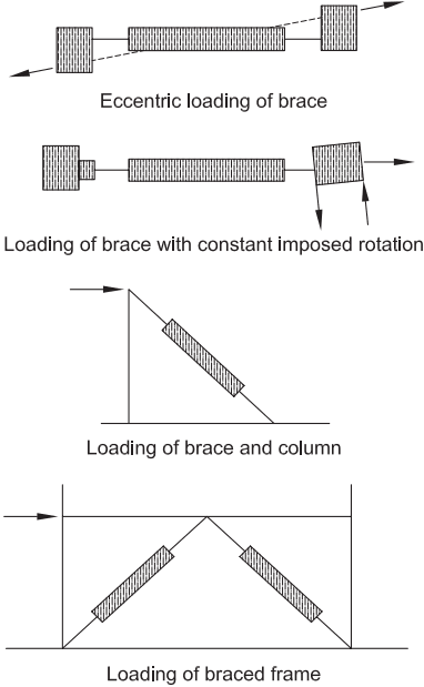
Figure description:
The image illustrates four possible test subassemblages for structural brace qualification:
- Eccentric loading of brace: A horizontal brace specimen subjected to axial force applied with an eccentricity.
- Loading of brace with constant imposed rotation: A horizontal brace specimen where one end is subjected to axial force and a constant rotational moment.
- Loading of brace and column: A single diagonal brace connected to a vertical column and a base, subjected to a lateral load at the top of the column.
- Loading of braced frame: A complete frame assembly with two diagonal braces in a chevron configuration, subjected to a lateral load at the top beam level.
Fig. C-K3.2. Possible test subassemblages.
two tests available to determine the factor of safety against overall brace buckling. It is not intended that the more conservative of these must be used in design. Testing facilities often are not large enough to test braces of sufficient length to determine accurate factors of safety for large capacity braces resulting in very conservative factors of safety for overall casing buckling. It is not intended that the more conservative factors of safety dictate design when a more representative subassemblage test is also available.
The subassemblage test specimen is required to undergo combined axial and rotational deformations similar to those in the prototype. It is recognized that identical braces, in different locations in the building, will undergo different maximum axial and rotational deformation demands. In addition, the maximum rotational and axial deformation demands may be different at each end of the brace. The engineer is expected to make simplifying assumptions to determine the most appropriate combination of rotational and axial deformation demands for the testing program.
Some subassemblage configurations will require that one deformation quantity be fixed while the other is varied as described in the test conditions discussed above. In such a case, the rotational quantity may be applied and maintained at the maximum value, and the axial deformation applied according to the required loading sequence. The engineer may wish to perform subsequent tests on the same subassemblage specimen to bound the brace performance.
K3.3 Brace Test Specimen
The objective of brace test specimen testing is to establish basic design parameters for the BRBF system.
The allowance of previous test data (similarity) to satisfy these provisions is less restrictive for uniaxial testing than for subassemblage testing. Subassemblage test specimen requirements are discussed in Commentary Section K3.2.
It is recognized that the fabrication tolerances used by brace manufacturers to achieve the required brace performance may be tighter than those used for other fabricated structural steel members. The engineer is cautioned against including excessively prescriptive brace specifications, as the intent of the Provisions is that the fabrication and supply of the braces is achieved through a performance-based specification process. It is considered sufficient that the manufacture of the test specimen and the prototype braces be conducted using the same quality control and assurance procedures, and the braces be designed using the same design methodology.
The engineer should also recognize that manufacturer process improvements over time may result in some manufacturing and quality control and assurance procedures changing between the time of manufacture of the brace test specimen and of the prototype. In such cases, reasonable judgment is required.
The intent is to allow test data from previous test programs to be presented where possible. See Commentary Section K3.2.
The intent of this provision is to ensure that the end connections of the brace test specimen reasonably represent those of the prototype. It is possible that due to fabrication or assembly constraints, variations in fit-up, faying-surface preparation, or bolt or pin hole fabrication and size may occur. In certain cases, such variations may not be detrimental to the qualification of a successful cyclic test. The final acceptability of variations in brace end connections rests on the opinion of the building official.
K3.4 Loading History
The loading sequence requires each tested brace to achieve ductilities corresponding to 2.0 times the design earthquake displacement and a cumulative inelastic axial ductility capacity of 200 times the yield displacement. Both of these requirements are based on a study in which a series of nonlinear dynamic analyses was conducted on model buildings in order to investigate the performance of this system. The ductility capacity requirement represents a mean of response values (Sabelli et al., 2003). The cumulative ductility requirement is significantly higher than expected for the design basis earthquake, but testing of braces has shown this value to be easily achieved. It is expected that, as more test data and building analysis results become available, these requirements may be revisited.
The ratio of brace yield deformation, , to the brace deformation corresponding to the design earthquake displacement, , must be calculated in order to define the testing protocol. This ratio is typically the same as the ratio of the displacement amplification factor (as defined in the applicable building code) to the actual overstrength of the brace; the minimum overstrength is determined by applying the resistance factor (LRFD) or the safety factor (ASD) in Section F4.5b.2.
Engineers should note that there is a minimum brace deformation at the design earthquake displacement, , corresponding to story drift. Providing overstrength beyond that required to limit the design earthquake displacement may not be used as a basis to reduce the testing protocol requirements. Testing to at least twice this minimum (in other words, to drift) is required.
Table C-K3.1 shows an example brace test protocol. For this example, it is assumed that the brace deformation corresponding to the design earthquake displacement is 4 times the yield deformation; it is also assumed that the design earthquake displacement is larger than the 1% minimum. The test protocol is then constructed in accordance with Section K3.4c. In order to calculate the cumulative inelastic deformation, the cycles are converted from multiples of brace deformation at the design earthquake displacement, , to multiples of brace yield deformation, . Because the cumulative inelastic drift at the end of the cycles is less than the minimum of required for brace tests, additional cycles to are required. At the end of four such cycles, the required cumulative inelastic deformation has been reached.
Dynamically applied loads are not required by the Provisions. The use of slowly applied cyclic loads, widely described in the literature for brace specimen tests, is acceptable for the purposes of these Provisions. It is recognized that dynamic loading can considerably increase the cost of testing and that few laboratory facilities have
TABLE C-K3.1
Example Brace Testing Protocol
| Step (Δbm) | Step (Δby)[a] | Cycles | Inelastic Deformation per Step | Cumulative Inelastic Deformation |
|---|---|---|---|---|
| Δby | Δby | 2 | =2(4)(Δby-Δby)=0Δby | 0Δby = 0Δby |
| 0.50Δbm | 2.0Δby | 2 | =2(4)(2Δby-Δby)=8Δby | 0Δby + 8Δby = 8Δby |
| 1.0Δbm | 4.0Δby | 2 | =2(4)(4Δby-Δby) = 24Δby | 8Δby + 24Δby = 32Δby |
| 1.5Δbm | 6.0Δby | 2 | =2(4)(6Δby-Δby) = 40Δby | 32Δby + 40Δby = 72Δby |
| 2.0Δbm | 8.0Δby | 2 | =2(4)(8Δby-Δby) = 56Δby | 72Δby + 56Δby = 128Δby |
| 1.5Δbm | 6.0Δby | 4 | =4(4)(6Δby-Δby) = 80Δby | 128Δby + 80Δby = 208Δby [b] |
[a] The table assumes that results in where brace deformation at the design earthquake displacement, in. (mm) brace yield deformation, in. (mm)
[b] Cumulative inelastic deformation at end of protocol = 208Δby
the capability to apply dynamic loads to large-scale test specimens. Furthermore, the available research on dynamic loading effects on steel test specimens has not demonstrated a compelling need for such testing.
If rate-of-loading effects are thought to be potentially significant for the steel core material used in the prototype, it may be possible to estimate the expected change in behavior by performing coupon tests at low (test cyclic) and high (dynamic earthquake) load rates. The results from brace tests would then be factored accordingly.
Slender BRB cores develop more higher-mode buckling wave crests and greater cumulative friction during compression loading, increasing the compression strength adjustment factor, β. However, friction also amplifies the local compressive strains at the core ends, potentially causing Poisson expansion to wedge or bind the core to the casing, further increasing β. Post-binding compressive forces are sensitive to the confinement provided by the casing and are outside the scope of these Provisions. Projects employing BRB with exceptionally long or thin rectangular core plates should account for these potential effects and seek guidance in literature.
K3.5 Instrumentation
Minimum instrumentation requirements are specified to permit determination of necessary data. It is expected that alternative instrumentation adequate for these purposes will be used in some cases.
K3.6 Materials Testing Requirements
Tension testing of the steel core material used in the manufacture of the test specimens is required. In general, there has been good agreement between coupon test results and observed tensile yield strengths in full-scale uniaxial tests. Material testing required by this section is consistent with that required for testing of beam-to-column moment connections. For further information on this topic, refer to Commentary Section K2.6.
K3.7 Test Reporting Requirements
The results reported are necessary for conformance demonstration and for determination of strain-hardening and compression-overstrength requirements. As nonlinear modeling becomes more common, the production of test data to calibrate nonlinear elements is becoming an important secondary function. Little data exists on the behavior of braces beyond their design range; such information can be useful in verifying the reliability of the system.
K3.8 Acceptance Criteria
The acceptance criteria are written so that the minimum testing data that must be submitted are at least one subassemblage test and at least one uniaxial test. In many cases, the subassemblage test specimen also qualifies as a brace test specimen provided the requirements of Section K3.3 are met. If project-specific subassemblage testing is to be performed, it may be simplest to perform two subassemblage tests to meet the requirements of this section. For the purposes of these requirements, a single subassemblage test incorporating two braces in a chevron or other configuration is also considered acceptable.
Depending on the means used to connect the test specimen to the subassemblage or test apparatus, and the instrumentation system used, bolt slip may appear in the load versus displacement history for some tests. This may appear as a series of downward spikes in the load versus displacement plot and is not generally a cause for concern, provided the behavior does not adversely affect the performance of the brace or brace connection.
These acceptance criteria are intended to be minimum requirements. The 1.5 limit in Section K3.8(d) is essentially a limitation on β based on available test data, where β is the compression strength adjustment factor. Currently available braces should be able to satisfy this requirement.