D2.1 General
Adequate behavior of connections of members in various systems in the seismic force-resisting system (SFRS) is established by satisfying one of the following general conditions:
- (a) Connections in some systems are verified by testing to ensure adequate performance [e.g., intermediate moment frames (IMF) and special moment frame (SMF) beam-to-column connections, and buckling restrained-braced frame (BRBF) brace-to-gusset connections].
- (b) Connections of members in some systems are designed to resist the required strength of the connected member or an adjoining member and therefore the maximum connection forces are limited by expected strength of a member (e.g., special concentrically braced frame and BRBF diagonal braces and eccentrically braced frame links).
(c) Connections of some members must be designed to resist forces based on the load combinations including the overstrength seismic load (e.g., column splices, collectors, and ordinary concentrically braced frame diagonal braces).
A review of the requirements of these Provisions and ASCE/SEI 7 indicates that connections in the SFRS satisfy at least one of the preceding conditions. Therefore, the requirement in the 2005 Provisions that the design of a connection ensures a ductile limit state was deleted in the 2010 Provisions.
D2.2 Bolted Joints
The potential for full reversal of design load and the likelihood of inelastic deformations of members and/or connected parts necessitates that pretensioned bolts be used in bolted joints in the SFRS. However, earthquake motions are such that slip cannot and need not be prevented in all cases, even with slip-critical connections. Accordingly, the Provisions call for bolted joints to be proportioned as pretensioned bearing joints but with faying surfaces prepared as for Class A or better slip-critical connections. That is, bolted connections can be proportioned with available strengths for bearing connections as long as the faying surfaces are still prepared to provide a minimum slip coefficient, . The resulting nominal amount of slip resistance may minimize damage in more moderate seismic events. This requirement is intended for joints where the faying surface is primarily subjected to shear. Where the faying surface is primarily subjected to tension or compression from seismic load effects, for example, in a bolted end-plate moment connection, the requirement for preparation of the faying surfaces may be relaxed.
It is an acceptable practice to designate bolted joints as slip-critical as a simplified means of specifying the requirements for pretensioned bolts with slip-critical faying surfaces. However, when the fabricator is permitted to design the connections, specifying that bolted joints must be designed as slip-critical may result needlessly in additional and/or larger bolts.
To prevent excessive deformations of bolted joints due to slip between the connected plies under earthquake motions, the use of holes in bolted joints in the SFRS is limited to standard holes and short-slotted holes with the direction of the slot perpendicular to the line of force. For connections where there is no transfer of seismic load effect by shear in the bolts in the joint, oversized holes and short-slotted holes are permitted. An example is a collector beam end connection using an end-plate connection. The axial force in the beam due to seismic load effects is transferred by either tension in the end connection or by bearing of the beam end through the connection. Gravity loads are transferred by bolt shear, but not seismic load effects.
An exception is provided for alternative hole types that are justified as a part of a tested assembly. Additionally, an exception allows the use of oversized holes in one ply of connections of diagonal bracing members in Sections F1, F2, F3, and F4 when the connection is designed as a slip-critical joint. The required strength for the limit state of bolt slip for the connection is specified in the applicable section. As reported in FEMA 355D (FEMA, 2000e), bolted joints with oversized holes in tested moment connections were found to behave as fully restrained connections for most practical applications. Bolted connections of diagonal bracing with oversized holes should behave similarly. Oversized holes in diagonal bracing connections with slip-critical bolts will provide additional tolerance for field connections yet should remain as slip-resistant for most seismic events. If the bolts did slip in the oversized holes in an extreme situation, the connections should still behave similarly to fully restrained connections. Story drifts may also increase slightly if bolts slip, and the effect of bolt slip should be considered in drift calculations. In order to minimize the amount of slip, oversized holes for bolts are limited to one ply of the connection. For large diameter bolts, the amount of slippage can also be minimized by limiting the oversized bolt hole size to a maximum of in. ( 5 mm ) greater than the bolt diameter, rather than the maximum diameter permitted by the Specification. The available slip resistance of bolts in oversized holes is reflected in the reduced available strength for oversized holes, per Specification Section J3.9. While there is no loss of pretension with bolts properly installed in oversized holes, the Specification for static applications reduces the available strength because of the larger slip that occurs at strength loads. The overall behavior of connections with oversized holes has been shown to be similar to those with standard holes (Kulak et al., 1987).
To prevent excessive deformations of bolted joints due to bearing on the connected material, the bearing and tearout strengths are limited to the option where deformation is a design consideration in Specification Section J3.11. The philosophical intent of this limitation in the Specification is to limit the bearing and tearout deformation to an approximate maximum of 1/4 in. (6 mm). It should be recognized, however, that the actual bearing load in a seismic event may be much larger than that anticipated in design, and the actual deformation of holes may exceed this theoretical limit. Nonetheless, this limit should effectively minimize damage in moderate seismic events. An exception is permitted for those bolted connections where the required force is determined by the capacity of a member or an adjacent member; for this condition, the connection force is unlikely to be exceeded significantly. Therefore, for this restriction, the bearing and tearout strengths may be increased to the values allowed in Specification Section J3.11, where deformation is not a design consideration. The consequences of the additional deformation should still be considered. For example, additional frame drift could occur in a moment frame with shallow beams and bolted flange plate connections where additional beam rotation is caused by the increased bolt deformation.
Connections or joints in which bolts in combination with welds resist a common force in a common shear plane are prohibited. Due to the potential for full load reversal and the likelihood of inelastic deformations in connecting plate elements, bolts may exceed their slip resistances under significant seismic loads. Welds that are in a common shear plane to these bolts will likely not deform sufficiently to allow the bolts to slip into bearing, particularly if subjected to cyclic load reversal. Consequently, the welds will tend to resist the entire force and may fail if they are not designed to do so. These Provisions prohibit bolts from sharing a force with welds in a common shear plane in all situations. In addition to prohibiting sharing of loads on a common faying surface, sharing of a common force between different elements in other conditions is also prohibited. For example, bracing connections at beam-to-column joints are often configured such that the vertical component of the brace is resisted by a combination of both the beam web and the gusset connections to the columns. Figure C-D2.1
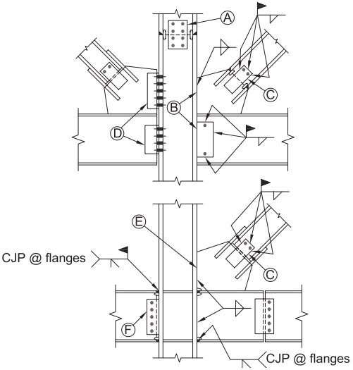
Figure description:
-
Figure C-D2.1 illustrates structural steel bracing connections at beam-to-column joints.
-
Key Entities & Labels:
- A: Bolted splice connection on a column.
- B: Gusset plate connections to a column and beam.
- C: Diagonal brace connection involving a gusset plate and bolts.
- D: Welded and bolted connection details for shear tabs.
- E: Continuous column member.
- F: Bolted beam-to-column web connection.
-
Welding Symbols:
- Includes symbols for fillet welds and field welds.
- CJP @ flanges: Specifies Complete Joint Penetration welds at the beam flanges.
-
A bolted web connection may be designed to resist column shear while welded flanges resist axial and/or flexural forces.
-
B Connection using both gusset and beam web welded to column allows both elements to participate in resisting the vertical component of the brace force. Note that erection bolts may be used to support beam temporarily.
-
Flanges and web are both welded to resist axial force in combination. Bolts are for erection only.
-
Both web of beam and gusset are bolted to column allowing sharing of vertical and horizontal forces.
-
A stub detail allows both gusset and beam web to be shop welded to column. Flanges of supported beam may be welded to transfer flexural and axial forces.
-
For beam moment connections, bolted webs can resist shear while welded flanges resist flexural and axial forces. (Moment connections must meet the requirements of Chapter E of the Provisions, as required.)
Fig. C-D2.1. Desirable details that avoid shared forces between welds and bolts.
illustrates desirable details, and Figure C-D2.2 illustrates problematic connections. Because these two elements are in a common shear plane with limited deformation capability, if one element were welded and the other bolted, the welded joint would likely resist all the force. By making the connections of these elements to the column either both bolted or both welded when considering an individual shear plane, both elements would likely participate in resisting the force. Similarly, wide-flange bracing connections should not be designed such that bolted web connections share in resisting the axial loads with welded flanges (or vice versa).
Bolts in one element of a member may be designed to resist a force in one direction, while other elements may be connected by welds to resist a force in a different direction or shear plane. For example, a beam-to-column moment connection may use welded flanges to transfer flexure and/or axial loads, while a bolted web connection transfers the beam shear. Similarly, column splices may transfer axial loads and/or flexure through flange welds with horizontal shear in the column web transferred through a bolted web connection. In both of these cases, there should be adequate
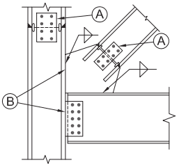
Figure description:
Structural Steel Connection Diagram
- Label A: Indicates bolted connections, specifically web and splice plates used to transfer shear or axial loads.
- Label B: Indicates welded connections, primarily at flange interfaces to transfer flexure or axial loads.
- Components Shown:
- Vertical Column: Features a splice joint (top left and connection points for lateral members.
- Horizontal Beam: Connected via welded flanges and a bolted web plate.
- Diagonal Member: Attached using a combination of welded plates and bolted connectors.
- Symbols: Welding symbols (triangular flags denote fillet welds at the junctions between horizontal/diagonal members and the column.
- A) Brace or column members should not be designed with a combination of bolted web and welded flanges resisting axial forces.
- B Brace connections to columns with gussets welded to the column and the beam web bolted to the column will transfer forces differently from all-welded or all-bolted connections. The welded joint of the gusset to the column will tend to resist the entire vertical force at the column face (the vertical component of the brace force, plus the beam reaction). Also, the transfer of horizontal force through the bolted web to the column face will be precluded by the stiffer path through the welded joints of the gusset, so the gusset-to-beam joint will tend to resist the entire horizontal component of the brace force. Pass-through forces at beam-column connection will bypass the shear plate and go through the gusset. Equilibrium of the connection requires additional moments in both the beam and column, as well as higher forces in the welds of the gusset to the column and to the beam to transfer these forces.
Fig. C-D2.2. Problematic bolted/welded member connections.
deformation capability between the flange and web connections to allow the bolts to resist loads in bearing independent of the welds.
The Provisions do not prohibit the use of erection bolts on a field-welded connection, such as a shear tab in the web of a wide-flange beam moment connection. In this instance, the bolts would resist the temporary erection loads, but the welds would need to be designed to resist the entire anticipated force in that element.
D2.3 Welded Joints
The general requirements for design of welded joints are specified in Specification Chapter J. Additional design requirements for specific systems or connection types are specified elsewhere in the Provisions. Requirements for weld filler metal toughness and welding procedures are specified in Sections A3.4 and I2.3.
D2.4 Continuity Plates and Stiffeners
The available lengths for welds of continuity plates and stiffeners to the web and flanges of rolled shapes are reduced by the detailing requirements of AWS D1.8/ D1.8M, clause 4.1 (AWS, 2021), as specified in Section I2.4 of the Provisions. See Figures C-D2.3(a) and (b). These large corner clips are necessary to avoid welding into the -area of wide-flange shapes. See Commentary Section A3.1 and AWS D1.8/ D1.8M, clause 4.1 commentary, for discussion.
D2.5 Column Splices
D2.5a Location of Splices
Column splices should be located away from the beam-to-column connection to reduce the effects of flexure. For typical buildings, the 4 ft (1.2 m) minimum distance requirement will control. When splices are located 4 to 5 ft (1.2 to 1.5 m) above the floor level, field erection and construction of the column splice will generally be
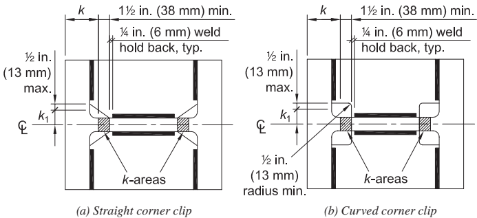
Figure description:
Figure C-D2.3: Configuration of continuity plates
Key Entities and Technical Specifications:
- Components: Column cross-sections featuring continuity plates with corner clips near the web-flange intersection (-areas.
- Configurations:
- (a Straight corner clip: Diagonal cut at the plate corner.
- (b Curved corner clip: Rounded radius at the plate corner.
- Dimensional Requirements:
- and : Standard design dimensions for the column section.
- Vertical clearance: maximum from the centerline to the start of the clip.
- Horizontal clearance: minimum clip width from the column flange face.
- Weld hold back: typical distance between the end of the weld and the corner clip.
- Curved clip radius: minimum.
- Purpose: Detailing to avoid welding in the -area of the column to reduce stress concentrations and potential cracking.
Fig. C-D2.3. Configuration of continuity plates.
simplified due to improved accessibility and convenience. In general, it is recommended that the splice be within the middle third of the story height from a design perspective. For less typical buildings, where the floor-to-floor height is insufficient to accommodate this requirement, the splice should be placed as close as practicable to the midpoint of the clear distance between the finished floor and the bottom flange of the beam above. It is not intended that these column splice requirements be in conflict with applicable safety regulations, such as the OSHA Safety Standards for Steel Erection (OSHA, 2010) developed by the Steel Erection Negotiated Rulemaking Advisory Committee (SEN-RAC). This requirement is not intended to apply at columns that begin at a floor level, such as a transfer column, or columns that are interrupted at floor levels by cantilevered beams. However, the splice connection strength requirements of Section D2.5 still apply.
D2.5b Required Strength
Except for moment frames, the available strength of a column splice in the SFRS is required to equal or exceed both the required strength determined in Section D2.5b and the required strength for axial, flexural, and shear effects at the splice location determined from load combinations stipulated by the applicable building code.
Partial-joint-penetration groove welded splices of thick column flanges exhibit virtually no ductility under tensile loading (Popov and Stephen, 1977; Bruneau et al., 1987). Consequently, column splices made with partial-joint-penetration (PJP) groove welds require a 100% increase in required strength and must be made using weld metal with minimum Charpy V-notch toughness properties from Section A3.4, unless the exception in Section D2.5b(b)(1) is satisfied.
The calculation of the minimum available strength in Section D2.5b(b)(2) includes the ratio . This results in a minimum available strength that is not less than 50% of the expected yield strength of the column flanges. A complete-joint-penetration (CJP) groove weld may be considered as satisfying this requirement. However, when applicable, tapered transitions are required in order to relieve stress concentrations where local yielding could occur at changes in column flange width or thickness per Section D2.5b(b)(3). Tensile stresses are to be calculated by adding the uniform axial stress with the elastic bending stress or stresses, using the elastic section modulus, .
The possible occurrence of tensile loads in column splices utilizing PJP groove welds during a maximum considered earthquake should be evaluated. When tensile loads are possible, it is suggested that some restraint be provided against relative lateral movement between the spliced column shafts because the strength of the PJP welds is potentially exhausted in resisting the tensile forces. For example, this can be achieved with the use of flange splice plates. Alternatively, web splice plates that are wide enough to maintain the general alignment of the spliced columns can be used. Shake-table experiments have shown that when columns that are unattached at the base reseat themselves after lifting, the performance of a steel frame remains tolerable (Huckelbridge and Clough, 1977).
These Provisions are applicable to common frame configurations. Additional considerations may be necessary when flexure dominates over axial compression in columns in moment frames and in end columns of tall narrow frames where overturning forces can be very significant. The designer should review the conditions found in columns in buildings with tall story heights when large changes in column sizes occur at the splice or when the possibility of column buckling in single curvature over multiple stories exists. In these and similar cases, special column splice requirements may be necessary.
Where CJP groove welds are not used, the connection is likely to consist of PJP groove welds. The unwelded portion of the PJP groove weld forms a discontinuity that acts like a notch that can induce stress concentrations. A PJP groove weld made from one side could produce an edge crack-like notch (Barsom and Rolfe, 1999). A PJP groove weld made from both sides would produce a buried crack-like notch. The strength of such internal crack-like notches may be computed by using fracture mechanics methodology. Depending on the specific characteristics of the particular design configuration, geometry, and deformation, the analysis may warrant elastic-plastic or plastic finite element analysis of the joint. The accuracy of the computed strength will depend on the finite element model and mesh size used, the assumed strength and fracture toughness of the base metal, the heat affected zone and weld metal, and the residual stress magnitude and distribution in the joint.
D2.5c Required Shear Strength
Inelastic analyses (FEMA, 2000d) of moment frame buildings have shown the importance of the columns that are not part of the SFRS in helping to distribute the seismic shears between the floors. Even columns that have beam connections considered to be pinned connections may develop large bending moments and shears due to non-uniform drifts of adjacent levels. For this reason, it is recommended that splices of such columns be adequate to develop the shear forces corresponding to these large column moments in both orthogonal directions. Accordingly, columns that are part of the SFRS must be connected for the greater of the forces resulting from these drifts or the requirements specific to the applicable system in Chapters E, F, G, or H.
FEMA 350 (FEMA, 2000a) recommends that “Splices of columns that are not part of the seismic force-resisting system should be made in the center one-third of the column height, and should have sufficient shear capacity in both orthogonal directions to maintain the alignment of the column at the maximum shear force that the column is capable of producing.” The corresponding commentary suggests that this shear should be calculated assuming plastic hinges at the ends of the columns in both orthogonal directions.
Further review of nonlinear analyses cited in FEMA 355C (FEMA, 2000e) showed that, in general, shears in such columns will be less than one-half of the shear calculated from , where is the plastic moment of the column and is the height of the story. For this reason, Section D2.5c requires that the calculated shear in the splices be .
D2.5d Structural Steel Splice Configurations
Bolted web connections are preferred by many engineers and contractors because they have advantages for erection, and when plates are placed on both sides of the web, whether they are bolted or welded, they are expected to maintain alignment of the column in the event of a flange splice fracture. A one-sided web plate may be used when it is designed as a backup plate for a CJP web weld. This plate is also commonly used as a column erection aid. In most cases, PJP groove welded webs are not recommended because fracture of a flange splice would likely lead to fracture of the web splice, considering the stress concentrations inherent in such welded joints. Requirements are given in Section E3.6g that apply to IMF, SMF, and special truss moment frames (STMF) allowing the use of PJP groove welds at the web splice.
Weld backing for groove welds in column splices may remain. The justification for this is that unlike beam-to-column connections, splices of column flanges and webs using weld backing result in no transversely loaded notch.
D2.6 Column Bases
Column bases must have adequate strength to permit the expected ductile behavior for which the system is designed in order for the anticipated performance to be achieved. Column bases are required to be designed for the same forces as those required for the members and connections framing into them. If the connections of the system are required to be designed for the amplified seismic loads or loads based on member strengths, the connection to the column base must also be designed for those loads.
Column bases are considered to be column splices. The required strength of column bases includes the requirements prescribed in Section D2.5. It is necessary to decompose the required tension strength of connections of diagonal brace members to determine the axial and shear forces imparted on the column base.
The requirement for removal of weld tabs and weld backing at column-to-base plate connections made with groove welds is included in Section D2.6 as it is applicable to all SFRS systems in Chapters E, F, G, and H. The use of weld backing for a CJP weld of a column to a base plate creates a transverse notch. Consequently, weld backing must be removed. For IMF and SMF systems, weld backing is allowed to remain at the CJP welds of the top flange of beam-to-column moment connections if a fillet weld is added per ANSI/AISC 358, Chapter 3 (AISC, 2022b). Similarly, an exception has been added for column bases to permit weld backing to remain at the inside flanges and at the webs of wide-flange shapes when a reinforcing fillet weld is added between the backing bar and the base plate.
D2.6a Required Axial Strength
The required axial (vertical) strength of the column base is computed from the column required strength in Sections D1.4a and D2.5b, in combination with the vertical component of the required connection strength of any braces present.
D2.6b Required Shear Strength
The required shear (horizontal) strength of the column base in the SFRS is computed from a mechanism in which the column forms plastic hinges at the top and bottom of the first story, in combination with the horizontal component of the required connection strength of any braces present. The component of shear in the column need not exceed the load effect corresponding to the overstrength seismic load. As noted in Commentary Section D2.5c, columns that are not part of the SFRS may be subject to significant shear loads from relative displacement between floors particularly if there are nonuniform drifts between floors. Similarly, bases of columns that are not part of the SFRS will be subject to high shear demand. A minimum shear requirement is present for all column bases, including columns that are not part of the SFRS. The required shear force for column bases is less than that for column splices given that the base level of gravity columns is typically pinned. This allows the column to develop a lesser shear from building drift than a column with fixity at both ends. An exception to the shear force given in Section D2.6b is allowed for single-story columns with simple connections at both ends as shear from story drift will not develop in columns where flexure cannot occur at either end.
An additional exception is added to reduce the minimum required shear force at the column base due to column flexure. The forces determined from a nonlinear analysis in accordance with Section C3 may be used to determine shear in the column.
Systems in Sections E1, F1, G1, H1, and H4 are expected to have limited inelastic behavior. Consequently, in these systems, shear forces in columns that are not part of the SFRS due to nonuniform drifts between the first and second story of a structure are expected to be minimal. Therefore, the minimum shear force is not required for these systems.
Alternatively, shear forces in the columns can be determined by an analysis that considers a drift of 0.025 times the story height at either the first level or the second level, but not both concurrently. This can be performed using a simple model of a cantilever column with a single backspan, as illustrated in Figure C-D2.4. The shear developed at the column base due to a deflection of can be determined. Of note, the shear forces caused by a given drift about the column weak axis are typically less than the strong axis.
There are several possible mechanisms for shear forces to be transferred from the column base into the supporting concrete foundation. Surface friction between the base plate and supporting grout and concrete is probably the initial load path, especially if the anchor rods have been pretensioned. Unless the shear force is accompanied by enough tension to completely overcome the dead loads on the base plate, this mechanism will probably resist some or all of the shear force. However, many building codes prescribe that friction cannot be considered when resisting code prescribed earthquake loads, and another design calculation method must be utilized. The other potential mechanisms are anchor rod bearing against the base plates, shear keys bearing on grout in the grout pocket, or bearing of the column embedded in a slab or grade beam. Figure C-D2.5 illustrates the four transfer mechanisms.
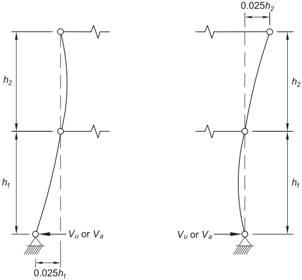
Figure description:
Structural Model for Column Drifts (Fig. C-D2.4
- Subject: Two-story vertical column models used to determine structural drift.
- Key Parameters:
- Story Heights: (lower story and (upper story.
- Forces: Applied shear forces denoted as or at the column joints.
- Drift/Offsets: Displacement magnitudes defined as (base level and (top level.
- Configurations:
- Left Model: Shows a horizontal offset of at the pinned base relative to the vertical centerline.
- Right Model: Shows a horizontal offset of at the top joint relative to the vertical centerline.
- Components: Pinned connections at joints, vertical column segments, and horizontal members extending from joints.
Fig. C-D2.4. Model to determine column drifts.
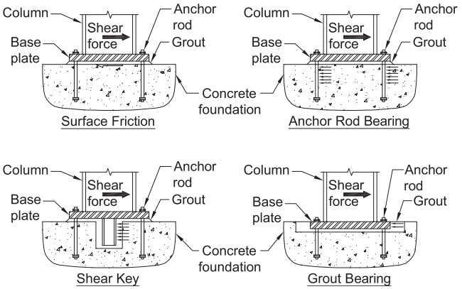
Figure description:
Key Entities:
- Structural Components: Column, Base plate, Anchor rod, Grout, Concrete foundation.
- Force: Shear force acting horizontally on the column.
Shear Transfer Mechanisms:
- Surface Friction: Resistance occurs at the horizontal interface between the grout/base plate and the concrete foundation.
- Anchor Rod Bearing: Shear is resisted by the lateral bearing of anchor rods against the internal concrete of the foundation.
- Shear Key: A vertical projection from the base plate into a foundation pocket provides resistance through bearing against the concrete.
- Grout Bearing: Resistance is provided by the base plate and grout bearing against the vertical face of a recess in the concrete foundation.
Fig. C-D2.5. Shear transfer mechanisms—column supported by foundation.
Anchor rod bearing is usually considered in design and is probably sufficient for light shear loads. It represents the shear limit state if the base plate has overcome friction and has displaced relative to the anchor rods. The anchor rods are usually checked for combined shear and tension. Anchor rod bearing on the base plate may also be considered, but usually the base plate is so thick that this is not a problem. Note that oversized holes are typically used for anchor rods, and a welded washer may be required to transmit forces from the base plate to the anchor rods. Where shear is transferred through the anchor rods, anchor rods are subjected to flexure.
A shear key should be considered for heavy shear loads, although welding and construction issues must be considered. If tension and/or overturning loads are present, anchor rods must also be provided to resist tension forces.
For foundations with large free edge distances, concrete blowout strength is controlled by concrete fracture; the concrete capacity design (CCD) method prescribed in ACI 318, Chapter 17, provides a relatively accurate estimate of shear key concrete strength. For foundations with smaller edge distances, shear key concrete blowout strength is controlled by concrete tensile strength; and the cone method prescribed in ACI 349 (ACI, 2006) and AISC Design Guide 1, Base Plate and Anchor Rod Design (AISC, 2010a), provides a reasonable estimate of shear key concrete strength. In recognition of limited physical testing of shear keys, it is recommended that the shear key concrete blowout strength be estimated by the lower of these two methods (Gomez et al., 2009).
Where columns are embedded, the bearing strength of the surrounding concrete can be utilized. Note that the concrete element must then be designed to resist this force and transfer it into other parts of the foundation or into the soil.
When the column base is embedded in the foundation, it can serve as a shear key to transfer shear forces. It is sometimes convenient to transfer shear forces to concrete grade beams through reinforcing steel welded to the column. Figure C-D2.6 shows two examples of shear transfer to a concrete grade beam. The reinforcing steel must be long enough to allow a splice with the grade beam reinforcing steel, allowing transfer of forces to additional foundations.
D2.6c Required Flexural Strength
Column bases required to be designed as moment connections can be of several different types, as follows:
-
(1) A rigid base assembly may be provided that is strong enough to force yielding in the column. The designer should employ the same guidelines as given for rigid fully restrained connections. Such connections may employ thick base plates, haunches, cover plates, or other strengthening as required to develop the column hinge. Where haunched-type connections are used, hinging occurs above the haunch, and appropriate consideration should be given to the stability of the column section at the hinge. See Figure C-D2.7 for examples of rigid-base assemblies that can be designed to be capable of forcing column hinging. In some cases, yielding can occur in the concrete grade beams rather than in the column. In this case, the concrete grade beams should be designed in conformance with ACI 318, Chapter 18.
-
(2) Large columns may be provided at the bottom level to limit the drift, and a "pinned base" may be utilized. The designer should ensure that the required shear capacity of the column, base plate, and anchor rods can be maintained up to the maximum rotation that may occur. It should be recognized, however, that without taking special measures, column base connections will generally provide partial rotational fixity.
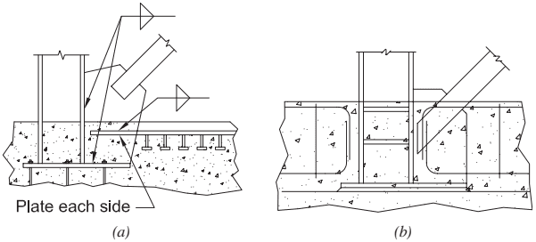
Figure description:
The image displays technical diagrams illustrating shear transfer mechanisms from steel members to a concrete grade beam.
Key Entities:
- Steel Column & Diagonal Brace: Primary structural members transferring loads.
- Concrete Grade Beam: The foundation element receiving the shear forces.
- Base Plate & Side Plates: Interface components for welding and load distribution.
- Shear Studs: Headed anchors in diagram (a used to transfer forces into the concrete.
- Reinforcement Bars (Rebar: Horizontal steel bars in diagram (b integrated within the grade beam.
Technical Details:
- Diagram (a: Features a connection using a surface base plate and an embedded horizontal plate equipped with headed shear studs. Weld symbols indicate fillet welds connecting the column, brace, and side plates.
- Diagram (b: Shows direct embedment of the steel column and brace into the concrete beam. This method utilizes internal column stiffeners and continuous horizontal reinforcement bars to facilitate shear transfer.
Fig. C-D2.6. Examples of shear transfer to a concrete grade beam.
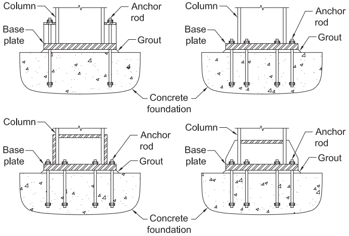
Figure description:
The image displays four diagrams of rigid-base plate assemblies for moment frames, illustrating different configurations for anchor rod placement and structural reinforcement.
Key Components:
- Column: The vertical structural steel member.
- Base plate: The thick horizontal plate at the bottom of the column.
- Anchor rod: Long bolts embedded in the concrete to secure the base plate.
- Grout: Material placed between the base plate and the concrete foundation for leveling and load distribution.
- Concrete foundation: The bottom structural support element.
Assembly Variations:
- Top-Left: External anchor rods with tall vertical sleeves or stiffeners outside the column profile.
- Top-Right: Multiple anchor rods placed both inside and outside the column flanges.
- Bottom-Left: Similar to top-right but features a horizontal internal stiffener plate within the column.
- Bottom-Right: Features external vertical stiffeners (gussets connecting the column to the base plate, with anchor rods positioned between them.
Fig. C-D2.7. Example of rigid-base plate assembly for moment frames.
- (3) According to the requirements of Section D2.6c(b)(2), the column base moment must be equal to or greater than the moment calculated using the overstrength seismic load. Because this moment is less than the flexural strength of the column, there is a need to ensure that a ductile limit state will occur in either the connection or the foundation to avoid connection failure. A connection that provides “partial fixity” may be provided, such that the column behaves as a fixed column up to some moment, whereupon the column base yields prior to the column hinging. This can be achieved through flexural bending of the base plate similar to an end-plate connection, bending of elements used as anchor chairs, ductile yielding of the foundation, uplift of the foundation, or elongation of the anchor rods. For the latter, ACI 318, Chapter 17, provides guidance to ensure anchor rod elongation prior to concrete breakout.
- (4) The column may continue below the assumed seismic base (e.g., into a basement, crawl space, or grade beam) in such a way that column fixity is assured without the need for a rigid base plate connection. The designer should recognize that hinging will occur in the column, just above the seismic base or in the grade beam. If hinging is considered to occur in the grade beam, then the grade beam should be designed in conformance with ACI 318, Chapter 18. The horizontal shear to be resisted at the ends of the column below the seismic base should be calculated considering the expected strength, , of the framing. See Figure C-D2.8 for examples of a column base fixed within a grade beam.
Based on experimental observations, the ultimate strength of the column base will be reached when any one of the following yielding scenarios is activated (Gomez et al., 2010):
- (1) Flexural yielding of both the tension side and compression side of the base plate
- (2) Axial yielding of the anchor rods on the tension side
- (3) Crushing of the concrete or grout
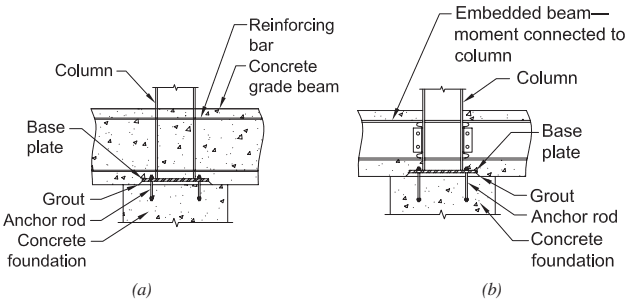
Figure description:
Fig. C-D2.8. Examples of column base fixity in a grade beam
Diagram (a:
- Column: Vertical structural member.
- Base Plate: Located at the bottom of the column.
- Anchor Rods: Secure the base plate to the concrete foundation.
- Grout: Layer between the base plate and the foundation.
- Concrete Grade Beam: Horizontal beam through which the column passes, containing reinforcing bars.
- Concrete Foundation: The base support structure.
Diagram (b:
- Embedded Beam: A horizontal beam moment-connected to the column within the grade beam.
- Column: Vertical structural member.
- Base Plate: Located at the bottom of the column.
- Anchor Rods: Secure the base plate to the concrete foundation.
- Grout: Layer between the base plate and the foundation.
- Concrete Foundation: The base support structure.
Fig. C-D2.8. Examples of column base fixity in a grade beam.
Historically, both triangular concrete stress blocks and rectangular concrete stress blocks have been used for the analysis of column base plates; the rectangular stress blocks give the best agreement with test results (Gomez et al., 2010).
D2.7 Composite Connections
The use of composite connections often simplifies some of the special challenges associated with traditional steel and concrete construction. For example, compared to structural steel, composite connections often avoid or minimize the use of field welding, and compared to reinforced concrete, there are fewer instances where anchorage and development of primary beam reinforcement is a problem.
Given the many alternative configurations of composite structures and connections, there are few standard details for connections in composite construction (Griffis, 1992; Goel, 1992c, 1993). However, tests are available for several connection details that are suitable for seismic design. References are given in this section and Commentary Chapters G and H. In most composite structures built to date, engineers have designed connections using basic mechanics, equilibrium, existing standards for steel and concrete construction, test data, and good judgment. The provisions in this section are intended to help standardize and improve design practice by establishing basic behavioral assumptions for developing design models that satisfy equilibrium of internal forces in the connection for seismic design.
General Requirements. The requirements for deformation capacity apply to both connections designed for gravity load only and connections that are part of the SFRS. The ductility requirement for gravity load only connections is intended to avoid failure in gravity connections that may have rotational restraint but limited rotation capacity. For example, Figure C-D2.9 shows a connection between a reinforced concrete wall and steel beam that is designed to resist gravity loads through shear and is not considered to be part of the SFRS. However, this connection is required to be designed to maintain its vertical shear strength under deformation demands, including rotations, which are imposed by inelastic seismic deformations of the structure.
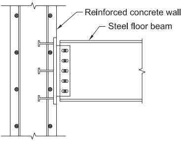
Figure description:
Structural Diagram: Steel Beam-to-Reinforced Concrete Wall Connection
Key Entities:
- Reinforced Concrete Wall: Structural vertical element containing reinforcement bars (circular icons and embedded hardware.
- Steel Floor Beam: Horizontal I-beam connected to the wall face.
- Embedded Plate: Steel plate cast into the concrete wall to facilitate the connection.
- Headed Studs: Three anchors shown extending from the embedded plate into the concrete for load transfer.
- Shear Tab: Vertical plate welded to the embedded plate and bolted to the beam web.
- Bolted Connection: Five bolts in slotted holes connecting the beam web to the shear tab.
Contextual Details:
- Function: Gravity load shear connection.
- Requirement: Designed to maintain vertical shear strength during structural rotations caused by inelastic seismic deformations, even though it is not part of the Seismic Force-Resisting System (SFRS.
Fig. C-D2.9. Steel beam-to-reinforced concrete wall gravity load shear connection.
In calculating the required strength of connections based on the nominal strength of the connected members, allowance should be made for all components of the members that may increase the nominal strength above that usually calculated in design. For example, this may occur in beams where the negative moment strength provided by slab reinforcement is often neglected in design but will increase the moments applied through the beam-to-column connection. Another example is in filled HSS braces where the increased tensile and compressive strength of the brace due to concrete should be considered in determining the required connection strength unless the fill does not engage the connection, which is preferred. Because the evaluation of such conditions is case specific, these Provisions do not specify any allowances to account for overstrength. However, as discussed in the Section A3.2 User Note, the provisions for each SFRS require that the required strength of connections, as a minimum, be based on the expected yield strength of the connected steel member or on the reinforcement in the connected concrete or composite member.
Nominal Strength of Connections. In general, forces between structural steel and concrete will be transferred by a combination of mechanical bond, adhesion, friction, and direct bearing. Transfers by bond and adhesion are not permitted for nominal strength calculation purposes because (1) these mechanisms are not effective in transferring load under inelastic load reversals and (2) the effectiveness of the transfer is highly variable depending on the surface conditions of the steel and shrinkage and consolidation of the concrete.
Transfer by friction should be calculated using the shear friction provisions in ACI 318, where the friction is provided by the clamping action of steel ties or studs or from compressive stresses under applied loads. Because the provisions for shear friction in ACI 318 are based largely on monotonic tests, the values are reduced by 25% where large inelastic stress reversals are expected. This reduction is considered to be a conservative requirement that does not appear in ACI 318 but is applied herein due to the relative lack of testing on configurations of composite structures.
In some composite connections, steel components are encased by concrete that will inhibit or fully prevent local buckling. For seismic design where inelastic load reversals are likely, concrete encasement will be effective only if it is properly confined. One method of confinement is with reinforcing bars that are fully anchored into the confined core of the member as required for column transverse reinforcement in ACI 318, Chapter 18. Adequate restraint may occur without closely spaced transverse reinforcement where the concrete cover is very thick. The effectiveness of the latter type of confinement should be substantiated by tests.
For fully encased connections between steel or composite beams and reinforced concrete or composite columns, such as shown in Figure C-D2.10, the panel-zone nominal shear strength can be calculated as the sum of contributions from the reinforced concrete and steel shear panels (see Figure C-D2.11). This superposition of strengths for calculating the panel-zone nominal shear strength is used in detailed design guidelines (Deierlein et al., 1989; ASCE, 1994; Parra-Montesinos and Wight, 2001) for composite connections that are supported by test data (Sheikh et al., 1989;
Kanno and Deierlein, 1997; Nishiyama et al., 1990; Parra-Montesinos and Wight, 2001). Further information on the use and design of such connections is included in Commentary Section G3.
Reinforcing bars in and around the joint region serve the dual functions of resisting calculated internal tension forces and providing confinement to the concrete. Internal tension forces can be calculated using established engineering models that satisfy equilibrium (e.g., classical beam-column theory, the truss analogy, and strut and tie models). Requirements for confinement (in other words, transverse reinforcement) usually are based on empirical models derived from test data and past performance of structures (Kitayama et al., 1987; ACI, 2002).
- (a) In connections such as those in composite partially restrained moment frames (C-PRMF), the force transfer between the concrete slab and the steel column requires careful detailing. For C-PRMF connections, such as shown in Figure C-D2.12, the strength of the concrete bearing against the column flange should be checked (Green et al., 2004). Only the solid portion of the slab, the area above the ribs, should be included in this calculation, and the nominal bearing strength should be limited to (Ammerman and Leon, 1990). In addition, because the force transfer requires the formation of a large compressive strut between the slab bars and the column flange, adequate transverse reinforcement should be provided in the slab to form the tension tie, such as traditional reinforcement. From equilibrium calculations, the area of transverse reinforcement should be the same as the longitudinal reinforcement and should extend at least 12 in. (300 mm) beyond either side of the effective slab width.
- (b) Due to the limited size of joints and the congestion of reinforcement, it often is difficult to provide the reinforcing bar anchorage for transverse column reinforcement in joints. Therefore, it is important to take into account the special requirements and recommendations for transverse reinforcement requirements (i.e., minimum area, spacing, and detailing) as specified for reinforced concrete connections in ACI 318, Chapter 18, and in ACI 352R (ACI, 2002), Kitayama
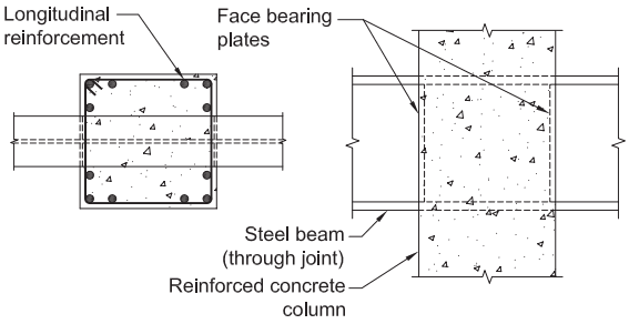
Figure description:
Key Entities & Components:
- Reinforced Concrete Column: Vertical structural member containing concrete and steel reinforcement.
- Steel Beam (Through Joint: Horizontal I-beam that passes continuously through the center of the concrete column joint.
- Longitudinal Reinforcement: Vertical rebar positioned around the perimeter of the column cross-section.
- Face Bearing Plates: Vertical plates attached to the beam at the column faces to transfer loads.
Structural Details:
- Plan View (Left: Shows the square column cross-section with a perimeter of 12 longitudinal rebars and the steel beam passing through the center.
- Elevation View (Right: Illustrates the vertical continuity of the column and the horizontal passage of the steel beam, secured with face bearing plates at the connection interface.
Fig. C-D2.10. Reinforced concrete column-to-steel beam moment connection.
et al. (1987), Sheikh and Uzumeri (1980), Park et al. (1982), and Saatcioglu (1991). Test data (Sheikh et al., 1989; Kanno and Deierlein, 1997; Nishiyama et al., 1990) on composite beam-to-column connections similar to the one shown in Figure C-D2.10 indicate that the face bearing plates attached to the steel beam provide effective concrete confinement.
- (c) As in reinforced concrete connections, large bond stress transfer of loads to column longitudinal bars passing through beam-to-column connections can result in slippage of the bars and bond damage under extreme loadings. Current practice for reinforced concrete connections is to control this slippage by
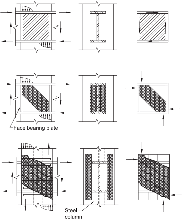
Figure description:
Key Information:
- Subject: Panel shear mechanisms in steel beam-to-reinforced concrete (RC column connections.
- Connection Components:
- Steel Beam: Horizontal members transferring loads to the column.
- RC Column: Vertical member supporting the beams.
- Face Bearing Plates: Specific plates used in the second mechanism to distribute beam flange loads into the concrete.
- Steel Column: An internal steel core shown in the third mechanism for enhanced shear capacity.
- Mechanical Actions:
- Force Distribution: Arrows indicate shear forces, moments (represented by horizontal tension/compression couples, and vertical bearing pressures.
- Shear Panel Behavior: Hatching patterns illustrate internal shear stresses and diagonal compression fields within the joint region.
- Stress Profiles: Parabolic distributions at the top and bottom of the joint represent concrete bearing stresses.
Fig. C-D2.11. Panel shear mechanisms in steel beam-to-reinforced concrete column connections (Deierlein et al., 1989).
limiting the ratio of the member depth (e.g., of the column) to the longitudinal bar diameter (e.g., of the beam) as described in ACI 352R.
At this time, there are no provisions herein for determining panel-zone shear strength; however, there is research that has been conducted on this subject. The following equations have been developed from research for calculating the panel-zone shear strength of filled composite members:
(C-D2-1)
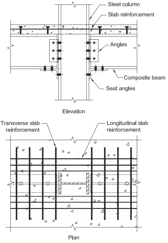
Figure description:
Entities and Components: Composite Partially Restrained Connection
Elevation View:
- Steel column: Central vertical structural support.
- Composite beam: Horizontal beams connected to the column.
- Slab reinforcement: Steel bars within the concrete slab above the beams.
- Angles: Connection plates bolted to the column flange and the beam webs.
- Seat angles: Support brackets bolted to the column flange and the bottom flange of the composite beams.
Plan View:
- Transverse slab reinforcement: Steel bars running perpendicular to the composite beams.
- Longitudinal slab reinforcement: Steel bars running parallel to the composite beams.
- H-shaped section: Cross-section of the central steel column surrounded by the slab and reinforcement grid.
Fig. C-D2.12. Composite partially restrained connection.
where
| Vc | = γAcp√f′c , kips (N) (C-D2-2) |
| γ | = 28 for rectangular filled columns = 24 for circular filled columns |
| Acp | = area of the concrete core engaged in the panel zone, in.2 (mm2) |
| Vst | = shear strength contribution of the filled composite column calculated using Specification Section I4.2, kips (N) |
| Vwn | = shear strength contribution of the web of the steel beam in through-beam connections calculated using Specification Equation G2-1, kips (N) |
The panel-zone shear strength equations for filled composite columns are based on the research conducted by Elremaily (2000) and Koester (2000). Fischer and Varma (2015) have illustrated the use of these equations.
D2.8 Steel Anchors
Experiments with steel headed stud anchors subjected to shear or a combination of shear and tension consistently show that a reduction in strength occurs with cycling, due primarily to the cyclic degradation of the concrete around the stud (McMullin and Astaneh-Asl, 1994; Civjan and Singh, 2003; Saari et al., 2004). Pallarés and Hajjar (2010a, 2010b) collected a wide range of test data of steel headed stud anchors subjected both to shear and combined shear and tension and documented that for composite members that are part of the SFRS in intermediate or special systems, a 25% reduction of the stud available strength given in the Specification is appropriate to allow for the effect of cyclic loads if the studs are expected to yield. Test data exists (Lee et al., 2005c; Wang et al., 2011) to confirm the available strength of steel headed stud anchors up to 1 in. (25 mm) in diameter when subjected to monotonic loading. However, the available cyclic test data was almost exclusively for steel headed stud anchors with diameters up to in. (19 mm). As such, these Provisions limit the diameter of steel headed stud anchors to in. (19 mm).