G4.1 Scope
Composite partially restrained moment frames (C-PRMF) consist of structural steel columns and composite steel beams connected with partially restrained (PR) composite joints (Leon and Kim, 2004; Thermou et al., 2004; Zandonini and Leon, 1992). In PR composite joints, flexural resistance is provided by a couple incorporating a conventional steel bottom flange connection (welded or bolted plates, angles, or T-stubs) and the continuous reinforcing steel in the slab at the top of the girder, as shown in Figure C-G4.1. The steel beam and the concrete slab are connected by steel anchors, such as steel headed anchor studs. Shear resistance is provided through a conventional steel frame shear connection (welded or bolted plates or angles). The use of the slab reinforcing steel results in a stronger and stiffer connection, a beneficial distribution of strength and stiffness between the positive and negative moment regions of the beams, and redistribution of loads under inelastic action. In most cases, the connections in this seismic force-resisting system at the roof level will not be designed as composite.
C-PRMF were originally proposed for areas of low to moderate seismicity in the eastern United States with seismic design categories A, B, and C; however, with appropriate detailing and analysis, C-PRMF can be used in areas of higher seismicity (Leon, 1990). Tests and analyses of these systems have demonstrated that the seismically induced loads on PR moment frames can be lower than those for fully restrained moment frames due to (a) lengthening in the natural period due to yielding in the connections and (b) stable hysteretic behavior of the connections (Nader and Astaneh-Asl, 1992; DiCorso et al., 1989). Thus, in some cases, C-PRMF can be designed for lower seismic loads than OMF.
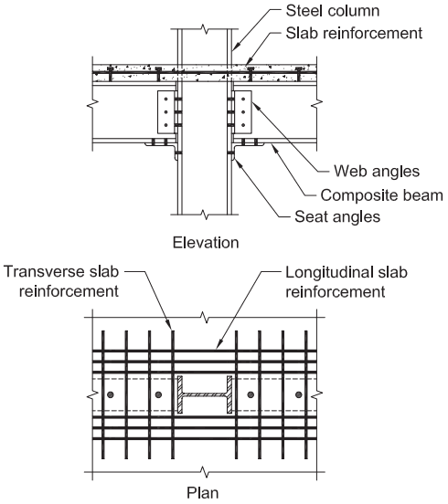
Figure description:
Subject: Composite partially restrained connection (C-PRMF
Elevation View Components:
- Steel column: Central vertical structural element.
- Slab reinforcement: Embedded horizontal bars within the concrete slab.
- Web angles: Connectors joining the beam web to the column flange.
- Composite beam: Horizontal structural member supporting the slab.
- Seat angles: Bottom brackets supporting the beam flange at the column interface.
Plan View Components:
- Transverse slab reinforcement: Rebar running perpendicular to the beam.
- Longitudinal slab reinforcement: Rebar running parallel to the beam.
- I-beam section: Shows the central steel column profile surrounded by the reinforcement grid.
Fig. C-G4.1. Composite partially restrained connection.
G4.2 Basis of Design
Design methodologies and standardized guidelines for C-PRMF and connections have been published (Ammerman and Leon, 1990; Leon and Forcier, 1992; Leon et al., 1996; ASCE, 1998). In the design of PR composite connections, it is assumed that bending and shear forces can be considered separately.
G4.3 Analysis
For frames up to four stories, the design of C-PRMF should be made using an analysis that, as a minimum, accounts for the PR behavior of the connections by utilizing linear springs with reduced stiffness (Bjorhovde, 1984). The effective connection stiffness should be considered for determining member load distributions and deflections, calculating the building’s period of vibration, and checking frame stability. Different connection stiffnesses may be required for these checks (Leon et al., 1996). Frame stability can be addressed using conventional procedures. However, the connection flexibility should be considered in determining the rotational restraint at the ends of the beams. For structures taller than four stories, drift and stability need to be carefully checked using analysis techniques that incorporate both geometric and connection nonlinearities (Rassati et al., 2004; Ammerman and Leon, 1990; Chen and Lui, 1991). Because the moments of inertia for composite beams in the negative and positive regions are different, the use of either value alone for the beam members in the analysis can lead to inaccuracies. Therefore, the use of a weighted average, as discussed in Specification Chapter I Commentary, is recommended (Zaremba, 1988; Ammerman and Leon, 1990; Leon and Ammerman, 1990; AISC, 2022d).
G4.4 System Requirements
The system should be designed to enforce a strong column-weak beam mechanism, except for at the roof level. Leon et al. (1996) suggest using the following equation, analogous to Equation E3-1 for SMF, to achieve this behavior:
(C-G4-1)
where is as defined in Section G3.4a and is the expected flexural strength of the PR connections framing into the joint. In calculating , appropriate factors for expected strength from Section A3.2 should be used. The value of 1.2 is intended so that a strong column-weak beam mechanism results.
G4.5 Members
G4.5a Columns
Column panel-zone checks in accordance with the Specification should be carried out assuming the connection moment is given by concentrated forces at the bottom flange and at the center of the concrete slab.
G4.5b Beams
Only fully composite beams are used in this system, as the effect of partial interaction in the composite beams has not been adequately justified. Because the force transfer relies on bearing of the concrete slab against the column flange, the bearing strength of the concrete should be checked. Figure C-G4.2 illustrates the forces involved in the slab bearing on the column flanges. The full nominal slab depth should be available for a distance of at least 12 in. (300 mm) from the column flange, as illustrated in Figure C-G4.3.
G4.6 Connections
The connecting elements should be designed with a yield force that is less than that of the connected members to prevent local limit states—such as local buckling of the flange in compression, web local crippling of the beam, panel-zone yielding in the column, and bolt or weld failures—from controlling. When these limit states are avoided, large connection ductility should result in excellent frame performance under large inelastic load reversals.
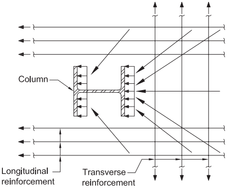
Figure description:
Key Information:
- Subject: Concrete slab bearing force transfer mechanism to a structural steel column.
- Column: Centrally located wide-flange (I-beam section.
- Reinforcement:
- Longitudinal reinforcement: Parallel horizontal bars with force arrows pointing away from the column.
- Transverse reinforcement: Vertical bars intersecting the longitudinal bars.
- Force Transfer:
- Diagonal arrows represent compressive forces acting towards the column flanges.
- Uniformly distributed load arrows indicate bearing pressure applied directly to the exterior faces of the column flanges.
Fig. C-G4.2. Concrete slab bearing force transfer.
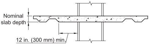
Figure description:
- Diagram Subject: Fig. C-G4.3. Solid slab to be provided around column.
- Key Entities:
- Concrete Slab: Features a variable profile (ribbed transitioning to a solid section at the column interface.
- Column: Vertical structural member passing through the slab.
- Nominal slab depth: Indicated as the full thickness from the top of the slab to the bottom of the ribs.
- Solid Slab Width Requirement: Minimum of 12 in. (300 mm of solid concrete slab extending from the face of the column before the ribbed profile begins.
Fig. C-G4.3. Solid slab to be provided around column.
G4.6c Beam-to-Column Connections
Most PR connections do not exhibit a simple elasto-plastic behavior and thus the moment strength of the connection must be tied to a connection rotation value. Most PR connections will achieve at least of their ultimate strength at this rotation level. The requirement is intended to apply to both positive and negative connection strength. This requirement is intended to prevent a potential incremental collapse mechanism from developing.
G4.6d Conformance Demonstration
Test results that show general conformance with Section K2 have been reported in the literature (Leon et al., 1987; Leon, 1994). Section K2 is written in terms of story drift rather than in terms of connection rotation; however, the intent of Section K2 for this seismic force-resisting system is to show that the connection is capable of sustaining cyclic strength through a connection rotation of 0.02 rad. Therefore, the loading sequence of Section K2.4b should be considered in the context of connection rotation rather than story drift and need only be taken through step (f) of the loading sequence.