F4.1 Scope
Buckling-restrained braced frames (BRBF) are a special class of concentrically braced frames. Just as in special concentrically braced frames (SCBF), the centerlines of BRBF members that meet at a joint intersect at a point to form a complete vertical truss system that resists lateral forces. BRBF have more ductility and energy absorption than SCBF because overall brace buckling, and its associated strength degradation, is precluded at forces and deformations corresponding to the design earthquake displacement. See Section F2 for the effects of buckling in SCBF. Figure C-F2.1 shows possible concentrically braced frame configurations; note that X-bracing is not an option for BRBF. As with SCBF, K-bracing is also not an option for BRBF. Figure C-F4.1 shows a schematic diagram of a BRBF bracing element (Tremblay et al., 1999).
- Basis of Design
BRBF are characterized by the ability of bracing elements to yield inelastically in compression as well as in tension. In BRBF, the bracing elements dissipate energy through stable tension-compression yield cycles (Clark et al., 1999). Figure C-F4.2 shows the characteristic hysteretic behavior for this type of brace as compared to that of a buckling brace. This behavior is achieved through limiting buckling of the steel core within the bracing elements. Axial stress is decoupled from flexural buckling resistance; axial load is confined to the steel core while the buckling restraining mechanism, typically a casing, resists overall brace buckling and restrains high-mode steel core buckling (rippling).
Buckling-restrained braced frames are composed of columns, beams, and bracing elements, all of which are subjected primarily to axial forces. Braces of BRBF, known as buckling-restrained braces (BRB), are composed of a steel core and a buckling-restraining system encasing the steel core. In addition to the schematic diagram shown in Figure C-F4.1, examples of BRB elements are found in Watanabe et al. (1988), Wada et al. (1994), and Clark et al. (1999). The steel core within the BRB is intended to be the primary source of energy dissipation. During a moderate to severe earthquake the steel core is expected to undergo significant inelastic deformations.
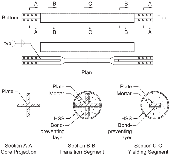
Figure description:
Subject: Engineering details of a buckling-restrained brace (BRB.
Key Components and Sections:
- Plan View: Illustrates the full assembly with bolted ends ("Bottom" and "Top" and cross-section markers for segments A-A, B-B, and C-C.
- Section A-A (Core Projection: Features a cruciform (cross-shaped steel plate core.
- Section B-B (Transition Segment:
- Core: Cruciform steel plate.
- Layering: Core is wrapped in a bond-preventing layer, encased in mortar, and housed within a circular HSS (Hollow Structural Section outer casing.
- Section C-C (Yielding Segment:
- Core: Flat rectangular steel plate.
- Layering: Same as Section B-B (bond-preventing layer, mortar infill, and outer HSS casing.
Key Entities:
- Steel Plate Core: Structural element that transitions from cruciform at ends to rectangular in the yielding zone.
- Mortar: Infill providing lateral support to prevent core buckling.
- HSS: Outer circular steel shell containing the mortar.
- Bond-preventing layer: Interface between the core and mortar to allow axial movement.
Fig. C-F4.1. Details of a type of buckling-restrained brace (Tremblay et al., 1999).
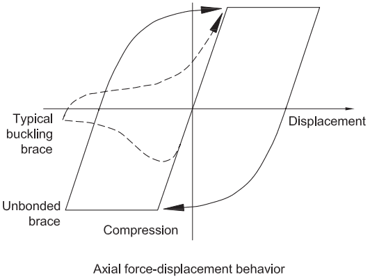
Figure description:
Axial force-displacement behavior
Axial force-displacement behavior
Legend
- Unbonded brace — color: black; symbol: Solid line
- Typical buckling brace — color: black; symbol: Dashed line
Annotations
- Typical buckling brace (text_label - position: points to the dashed line loop)
- Unbonded brace (text_label - position: points to the solid line loop)
- Compression (text_label - position: negative y-axis region)
- Displacement (text_label - position: positive x-axis)
- Loading direction arrow (top (arrow - position: top plateau of unbonded brace, pointing right))
- Loading direction arrow (bottom (arrow - position: bottom plateau of unbonded brace, pointing left))
- Loading direction arrow (buckling (arrow - position: reloading portion of dashed line, pointing up-right))
| Series | Displacement (relative) | Axial Force (relative) |
|---|---|---|
| Unbonded brace | -8.0 | -8.0 |
| Unbonded brace | -2.0 | -8.0 |
| Unbonded brace | 4.0 | 8.0 |
| Unbonded brace | 8.0 | 8.0 |
| Unbonded brace | 2.0 | -8.0 |
| Unbonded brace | -8.0 | -8.0 |
| Typical buckling brace | 8.0 | 8.0 |
| Typical buckling brace | 4.0 | 8.0 |
| Typical buckling brace | 0.0 | 1.0 |
| Typical buckling brace | -3.0 | -1.0 |
| Typical buckling brace | -5.0 | -4.0 |
| Typical buckling brace | -8.0 | -1.5 |
| Typical buckling brace | -5.0 | 1.0 |
| Typical buckling brace | -2.0 | 2.0 |
| Typical buckling brace | 1.0 | 7.0 |
| Typical buckling brace | 4.0 | 8.0 |
Notes: The chart illustrates the hysteresis loops for two types of structural braces. The unbonded brace exhibits a stable, symmetric energy-dissipating loop. The typical buckling brace shows a significant loss of compressive strength due to buckling, resulting in a 'pinched' hysteresis loop in the compression quadrant.
Fig. C-F4.2. Typical buckling-restrained (unbonded) brace hysteretic behavior (courtesy of Seismic Isolation Engineering).
BRBF can provide elastic stiffness that is comparable to that of EBF. Full-scale laboratory tests indicate that properly designed and detailed bracing elements of BRBF exhibit symmetrical and stable hysteretic behavior under tensile and compressive forces through significant inelastic deformations (Watanabe et al., 1988; Wada et al., 1998; Clark et al., 1999; Tremblay et al., 1999). The ductility and energy dissipation capability of BRBF is expected to be comparable to that of a special moment frame (SMF) and greater than that of an SCBF. This high ductility is attained by limiting buckling of the steel core.
The Provisions are based on the use of brace designs qualified by testing. They are intended to be used only within the proven range of deformation capacity and where yield and failure modes other than stable brace yielding are precluded at the maximum inelastic drifts corresponding to the design earthquake. For analyses performed using linear methods, the maximum inelastic drifts for this system are defined as those corresponding to 200% of the design earthquake displacement. For nonlinear time history analyses, the maximum inelastic drifts can be taken directly from the analysis results. A minimum of 2% story drift is required for determining expected brace deformations for testing (see Sections F4.2 and K3) and is recommended for detailing. This approach is consistent with the linear analysis equations for design story drift in ASCE/SEI 7 and the 2009 NEHRP Recommended Provisions (FEMA P-750) (FEMA, 2009a). It is also noted that the consequences of loss of connection stability due to the actual seismic displacements exceeding the calculated values may be severe; braces are therefore required to have a larger deformation capacity than directly indicated by linear static analysis.
The value of 200% of the design earthquake displacement for expected brace deformations represents the mean of the maximum story response for ground motions having a 10% chance of exceedance in 50 years (Fahnestock et al., 2003; Sabelli et al., 2003). Near-fault ground motions, as well as stronger ground motions, can impose deformation demands on braces larger than those required by the Provisions. While exceeding the brace design deformation may result in poor brace behavior, such as buckling, this is not equivalent to collapse. Detailing and testing braces for larger deformations will provide higher reliability and better performance.
The design engineer utilizing these provisions is strongly encouraged to consider the effects of configuration and proportioning of braces on the potential formation of building yield mechanisms. The axial yield strength of the core, , can be set precisely with the final core cross-sectional area determined by dividing the specified brace capacity by the actual material yield strength established by coupon testing, multiplied by the resistance factor. In some cases, the cross-sectional area will be governed by brace stiffness requirements to limit drift. In either case, careful proportioning of braces can make yielding distributed over the building height much more likely than in conventional braced frames.
It is also recommended that engineers refer to the following documents to gain further understanding of this system: Uang and Nakashima (2003); Watanabe et al. (1988); Reina and Normile (1997); Clark et al. (1999); Tremblay et al. (1999); and Kalyanaraman et al. (1998).
The design provisions for BRBF are predicated on reliable brace performance. In order to obtain this performance, a quality assurance plan is required. These measures are in addition to those covered in the AISC Code of Standard Practice for Steel Buildings and Bridges (AISC, 2022a) and Specification Chapters J and N. Examples of measures that may provide quality assurance are as follows:
- (a) Special inspection of brace fabrication. Inspection may include confirmation of fabrication and alignment tolerances, as well as nondestructive testing (NDT) methods for evaluation of the final product.
- (b) Brace manufacturer's participation in a recognized quality certification program. Certification should include documentation that the manufacturer's quality assurance plan is in compliance with the requirements of the Specification, the Provisions, and the Code of Standard Practice. The manufacturing and quality control procedures should be equivalent to, or better than, those used to manufacture brace test specimens.
F4.2 Basis of Design
F4.2a Brace Strength
Testing of braces is considered necessary for this system to ensure proper behavior. The applicability of tests to the designed brace is defined in Section K3.
Tests cited serve another function in the design of BRBF: The maximum forces that the brace can develop in the system are determined from test results. These maximum forces are used in the analysis required in Section F4.3.
F4.2b Adjustment Factors
The compression strength adjustment factor, , accounts for the compression overstrength with respect to tension strength noted in testing of buckling-restrained braces (SIE, 1999a, 1999b). The strain hardening adjustment factor, , accounts for strain hardening. Figure C-F4.3 shows a diagram of the bilinear force-displacement relationship in which the compression strength adjustment factor, , and the strainhardening adjustment factor, , are related to brace forces and nominal material yield strength. These quantities are defined as
(C-F4-1)
(C-F4-2)
where
cross-sectional area of the yielding segment of steel core, in.
maximum compression force, kips (N)
maximum tension force within deformations corresponding to of the design earthquake displacement (these deformations are defined as in Section K3.4c), kips (N)
Note that the specified minimum yield stress of the steel core, , is not typically used for establishing these factors; instead, is used, which is determined by the coupon tests required to demonstrate compliance with Section K3. Braces with values of and less than unity are not true buckling-restrained braces, and their use is precluded by Sections F4.2b and K3.8.
The expected brace strengths used in the design of connections and of beams and columns are adjusted upward for various sources of overstrength, including amplification due to expected material strength, using the ratio , in addition to the strain hardening, , and compression adjustment, , factors discussed previously. The amplification due to expected material strength can be eliminated if the brace yield stress is determined by a coupon test and is used to size the steel core area to provide the desired available strength precisely. Coupon testing, where used, should be performed at the point of manufacture on each plate used for the fabrication of BRB yielding cores. The use of mill test report results is not equivalent to a coupon test. Where core plates are fabricated from bar stock, coupons should be made at intervals of, at most, each 5 tons of material of the same heat and thickness. Other sources of overstrength, such as imprecision in the provision of the steel core area, may need to be considered; fabrication tolerance for the steel core is typically negligible.
F4.3 Analysis
Beams and columns are required to be designed considering the maximum force that the adjoining braces are expected to develop. Where frames intersect, loading on the shared column should address the development of these forces in both frames.
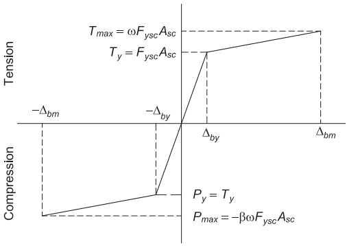
Figure description:
Annotations
- Tension (text_label - position: positive y-axis)
- Compression (text_label - position: negative y-axis)
| Displacement | Force |
|---|---|
| 0 | 0 |
Notes: The figure illustrates a idealized force-displacement relationship (backbone curve for a structural component such as a buckling-restrained brace. It defines key parameters for yield and maximum strength in both tension and compression, using horizontal and vertical reference lines to identify coordinates.)
Fig. C-F4.3. Diagram of brace force-displacement.
F4.4 System Requirements
F4.4a V- and Inverted V-Braced Frames
In SCBF, V-bracing has been characterized by a change in deformation mode after one of the braces buckles. This is primarily due to the negative post-buckling stiffness, as well as the difference between tension and compression capacity of traditional braces. Because buckling-restrained braces do not lose strength due to buckling and have only a small difference between tension and compression capacity, the practical requirements of the design provisions for this configuration are relatively minor. Figure C-F4.4 shows the effect of beam vertical displacement under the unbalanced load caused by the brace compression overstrength. The vertical beam deflection adds to the deformation demand on the braces, causing them to elongate more than they compress due to higher compression strength compared to tension strength. Therefore, where V-braced frames are used, it is required that a beam be provided that has sufficient strength to permit the yielding of both braces within a reasonable story drift, considering the difference in tension and compression capacities determined by testing. The required brace deformation capacity must include the additional deformation due to beam deflection under this load. Because other requirements, such as the brace testing protocol addressed in Section K3.4c and the stability of connections addressed in Section F4.6, depend on this deformation, engineers will find significant incentive to avoid flexible beams in this configuration. Where the special configurations shown in Figure C-F2.3 are used, the requirements of this section are not relevant.
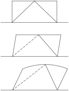
Figure description:
Key Entities:
- Columns
- Top beam
- Inverted-V braces
Deformation Stages:
- Top Diagram: Initial undeformed state of the inverted-V braced frame.
- Middle Diagram: Lateral drift deformation where the frame undergoes horizontal sway while the top beam remains straight.
- Bottom Diagram: Post-yield deformation mode showing significant lateral drift combined with downward vertical deflection of the top beam at the brace connection point.
- Significance: Illustrates how vertical beam deflection increases total brace deformation demand due to unbalanced forces between tension and compression braces.
Fig. C-F4.4. Post-yield change in deformation mode for inverted-V BRBF.
F4.4b K-Braced Frames
K-braced frames are not permitted for BRBF due to the possibility of inelastic flexural demands on columns.
F4.4d Multi-Tiered Braced Frames
Multi-tiered braced frames (MTBF) are defined as braced frame configurations with two or more tiers of bracing between diaphragm levels or locations of out-of-plane support. These tiers each incorporate a strut or beam at each tier of bracing and are therefore not classified as K-braced frames. The strut required by these Provisions spans between frame columns, though a strut exterior to the frame can be incorporated as part of the design of the frame to resist in-plane moments from the analysis requirements.
In the multi-tiered BRBF system (MT-BRBF), in-plane column demands are imposed by varying tier capacities and unbalanced brace loads created by the difference between the BRB overstrength in tension and compression. Studies done by Imanpour et al. (2015, 2016a, 2016b) have shown BRBF frames to be the most stable of the MTBF configurations explored to date. In these studies, the MT-BRBF has not demonstrated a single-tier mechanism, but some brace overstrength variation may occur from tier to tier. If the column or other resisting framework is not sufficient to support these loads, in-plane column yielding may occur. See Commentary Section F2.4e for additional information. Although this phenomenon was studied for the SCBF and demonstrated primarily during a concentration of drift in a critical tier, the same precautions are being recommended for the BRBF as have been proposed for the SCBF to mitigate the potential column instability. The requirement for column torsional bracing at each brace connection location satisfying the requirements developed by Helwig and Yura (1999), which may be provided by the flexural stiffness of the tier strut, is necessary to provide stability to the column. Previous editions of the Provisions included a separate requirement to consider the effects of out-of-plane forces due to the mass of the structure and supported items in combination with the forces obtained from the analyses required in this section. The consideration of forces in multiple directions and from multiple sources is a design requirement for all seismic force-resisting systems (SFRS) and is not specific to MT-BRBF systems. While required for all SFRS, consideration here could be particularly critical for multi-tiered braced frame systems.
The Provisions allow for the design of MT-BRB F using similar design requirements as are used for typical BRBF frames. Adjusted brace strengths are determined for each tier and used for design of the struts and columns in the frame. Unlike the typical building case, for multi-tiered braced frames, tiers with varied capacities or the possibility of an overstrength imbalance between tiers will require the column to work in flexure. Imanpour and Tremblay (2014) found that the application of adjusted brace strengths to the MT-BRBF frame overpredicts potential bending moments in the frame columns. However, the unique case where each tier is identical and braces are inclined in the same direction results in the applied moments in the columns being zero, a condition that would be unconservative. To address this, the minimum notional load requirement of 0.5% of the adjusted brace tier strength of each tier is included in the design provisions.
With an in-plane load at each tier level, the static-equilibrium method may then be followed with the columns treated as members spanning simply supported between the base and top of the MT-BRBF frame. The resulting method of adjusted brace strengths and the 0.5% minimum notional load provides for column moments that may be incurred due to a variation in the strains in the braces, tolerances on the core cut widths, and possible small variations between the independently tested core yield strengths and the final core yield strength. However, it may not provide for column moments that may be incurred due to tier capacity differences caused by or the specification of braces using a fixed area and a range of permitted yield strengths of the core material. Although there is no evidence that this material variation is detrimental to the MT-BRBF, a factor to account for the range of expected yield strengths of the braces has been included in the Provisions. The specification of the BRB by required capacity, , rather than by core area, , is a simple method to control the capacity of each tier such that the tier capacities are similar in a given frame, and column bending moments in the plane of the frame are reduced.
In Figure C-F4.5, “ABS” indicates unbalanced loads applied to the columns due to variation in adjusted brace strengths, and “NOT” indicates the required notional loads. Only the first and the fourth tier levels in this example have unbalanced loads due to adjusted brace strengths alone, and these loads are greater than the minimum notional load. NOT loads are applied in the direction producing the maximum moment on the column and analysis considers seismic loads in each direction.
A series of columns may be used to support the loads from this analysis. In this case, these must be designed for the portion of in-plane loads at tier levels combined with the axial compression on the column.
F4.4e Overall Stability of BRB and Connection Assemblies
Recent testing in stability and fracture has demonstrated that overall stability of the BRB and connections is a critical aspect of the design of BRBF (Tsai et al., 2003; Lopez et al., 2004; Takeuchi et al., 2014). The tendency to instability may vary depending on the initial out-of-straightness of the BRB and gusset, amplification of this out-of-straightness due to the manufacturer’s debonding gap, the flexural stiffness of the connection portions of the BRB, the degree of their flexural continuity with the casing (which is dependent on the effectiveness of the BRB neck’s development into the casing), and the stiffness of the casing itself. Note that the geometric imperfections of the external casing tube are not necessarily equal to those of the encased steel core. As destabilizing demands are primarily generated in the axially loaded steel core, geometric imperfections of the steel core are of greater interest to global stability of BRB. This aspect of BRBF design is the subject of continuing investigation, and designers are encouraged to consult Zaboli et al. (2018) and other research publications as they become available. The global stability of BRB and their gussets may be demonstrated with calculations or finite element analyses that consider the items listed in this section or by testing if the test specimen adequately resembles the conditions in the building. It is worth noting that during an earthquake, the frame may be subjected to some out-of-plane displacement concurrent with the in-plane deformations, and considering this in design may be warranted.
F4.5 Members
F4.5a Basic Requirements
The 2005 and 2010 editions of these Provisions required highly ductile sections for beams and columns. The requirement was then changed to moderately ductile sections in the 2016 edition. Because columns in BRBF are not only subjected to high axial forces but are also likely to experience inelastic rotations at the design earthquake displacement (Palmer et al., 2014), it is prudent that columns be designed for highly ductile requirements, which is reflected in the current provisions. This revision also aligns the column ductility requirements across SCBF, EBF, and BRBF.
F4.5b Diagonal Braces
- Assembly
- (a) Steel core
The steel core is composed of a yielding segment and steel core projections; it may also contain transition segments between the projections and
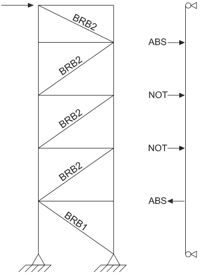
Figure description:
Key Information:
- Structure: MT-BRBF (Multi-Tiered Buckling Restrained Braced Frame elevation.
- Components:
- Braces: Labeled as BRB1 (bottom tier and BRB2 (upper four tiers.
- Frame: Five-tier vertical steel frame with horizontal struts and diagonal bracing.
- Supports: Fixed/pinned base supports at the bottom of the main frame.
- Force/Analysis Diagram (Right:
- ABS: Indicates "Adjusted Brace Stiffness" or similar applied force points.
- NOT: Indicates "Notional" force points.
- Boundary Conditions: Pinned supports at the top and bottom of the representative vertical line.
- Lateral Loading: Indicated by a horizontal arrow at the top-left corner of the frame.
Fig. C-F4.5. MT-BRBF elevation.
yielding segment. The cross-sectional area of the yielding segment of the steel core is expected to be sized so that its yield strength is fairly close to the demand calculated from the applicable building code. Designing all braces close to the required strengths will help facilitate distribution of yielding over multiple stories in the building. Conversely, over-designing some braces more than others (e.g., by using the same size brace on all floors) may result in an undesirable concentration of inelastic deformations in only a few stories. The length and area of the yielding segment, in conjunction with the lengths and areas of the nonyielding segments, determine the stiffness of the brace. The yielding segment length and brace inclination also determines the strain demand corresponding to the design earthquake displacement.
In typical brace designs, a projection of the steel core beyond its casing is necessary in order to accomplish a connection to the frame. Buckling of this unrestrained zone is an undesirable failure mode and must therefore be precluded.
In typical practice, the designer specifies the core plate dimensions as well as the steel material and grade. The steel stress-strain characteristics may vary significantly within the range permitted by the steel specification, potentially resulting in significant brace overstrength. This overstrength must be addressed in the design of connections as well as of frame beams and columns. The designer may specify a limited range of acceptable yield stress in order to more strictly define the permissible range of brace capacity. Alternatively, the designer may specify a limited range of acceptable yield stress if this approach is followed in order to more strictly define the permissible range of core plate area and the resulting brace stiffness. The brace supplier may then select the final core plate dimensions to meet the capacity requirement using the results of a coupon test. The designer should be aware that this approach may result in a deviation from the calculated brace axial stiffness. The maximum magnitude of the deviation is dependent on the range of acceptable material yield stress. Designers following this approach should consider the possible range of stiffness in the building analysis to adequately address both the building period and expected drift.
The strength of the steel core has been defined in terms of , which is defined as either the specified minimum yield stress of the steel core, or actual yield stress of the steel core as determined from a coupon test. The use of coupon tests in establishing eliminates the necessity of using in calculating the adjusted brace strength (see Commentary Section F4.2a). This is in recognition of the fact that coupon testing of the steel core material is in effect required by the similitude provisions in Section K3, and such coupon tests can provide a more reliable estimation of expected strength.
(b) Buckling-restraining system
- This term describes those elements providing brace stability against overall buckling. This includes the casing as well as elements connecting the core. The adequacy of the buckling-restraining system must be demonstrated by testing.
F4.5b.2 Available Strength
The nominal strength of buckling-restrained braces is simply based on the core area and the material yield strength. Buckling is precluded, as is demonstrated by testing.
F4.5b.3 Conformance Demonstration
BRBF designs require reference to successful tests of a similarly sized test specimen and of a brace subassemblage that includes rotational demands. The former is a uniaxial test intended to demonstrate adequate brace hysteretic behavior. The latter is intended to verify the general brace design concept and demonstrate that the rotations associated with frame deformations do not cause failure of the steel core projection, binding of the steel core to the casing, or otherwise compromise the brace hysteretic behavior. A single test may qualify as both a subassemblage and a brace test subject to the requirements of Section K3; for certain frame-type subassemblage tests, obtaining brace axial forces may prove difficult and separate brace tests may be necessary. A sample test subassemblage is shown in Figure C-K3.1 (Tremblay et al., 1999).
References to successful tests must be within the limits specified for subassemblage and brace test specimens specified in Sections K3.2 and K3.3. The intent of these limits is to help make the design and configuration of the tested specimen representative of those that will be present in the prototype and that the extrapolation range is reasonably centered on the prototype test specimen. A requirement was added in the 2022 Provisions to provide a bottom end on the downward extrapolation for small-capacity braces where their behavior may become a concern and may differ more significantly from larger capacity test specimens. This addition results in a test specimen with a steel core axial yield strength that is no more than 120% of the prototype, effectively reducing the extrapolation range for these lower-capacity prototypes. In previous versions of the Provisions, the extrapolation range for all braces was limited in a similar manner, but this restricted limitation is not deemed to be necessary except at the lower limits of tested ranges.
F4.5c Protected Zones
The core, as the expected region of inelastic strain, is a protected zone along with all elements connecting the core to the beams and columns, which may include gusset plates and gusset connections.
F4.6 Connections
F4.6a Demand Critical Welds
Inelastic strain in the weld material is likely at column base plates and column splices. Thus, these are required to be treated as demand critical welds. See Commentary Section F2.6a.
F4.6b Beam-to-Column Connections
See Commentary Section F2.6b.
F4.6c Diagonal Brace Connections
Bracing connections must not yield at force levels corresponding to the yielding of the steel core; they are therefore designed for the maximum force that can be expected from the brace (see Commentary Section F4.5b). The engineer should recognize that the bolts are likely to slip at forces 30% lower than their available strength. This slippage is not considered to be detrimental to behavior of the BRBF system and is consistent with the design approach found in Section D2.2.
Fahnestock et al. (2006) tested a connection, shown in Figure C-F4.6, that effectively provided a pin in the beam outside of the gusset plate via the splice with a WT section on each side. In addition to satisfying the requirements of Section F4.6b, this connection relieves the gusset plate of in-plane moments and the related destabilization effects.
Refer to Commentary Section F4.4e for discussion of the combined stability require- ment of the gusset plate and the BRB, as well as the interaction between these two elements.
F4.6d Column Splices
See Commentary Section F2.6d.