The coupled composite plate shear walls-concrete filled (CC-PSW/CF) system is included in ASCE/SEI 7, Table 12.2-1 (ASCE, 2022), and FEMA P-2082-1, Table 12.2-1 (FEMA, 2020), and is also new to the 2022 edition of these Provisions. This coupled shear wall system is composed of composite plate shear walls coupled together by composite coupling beams. The composite walls are like the C-PSW/CF of Section H7. The coupling beams are generally built-up steel box sections with concrete infill. Some schematic examples of CC-PSW/CF systems are shown in Figure C-H8.1. AISC Design Guide 38, SpeedCore Systems for Steel Structures (Varma et al., 2022), presents detailed explanations and examples of the capacity design principle recommended for the CC-PSW/CF systems.
H8.1 Scope
CC-PSW/CF are an alternative to coupled reinforced concrete shear walls or SPSW, especially when relatively large seismic demand on the walls leads to dense reinforcement and large thicknesses in conventional concrete shear walls and coupling beams or to relatively large wall thicknesses of the web infill and boundary elements in coupled SPSW. The limits set forth in the scope are associated with the range of parameters considered in the investigations conducted on CC-PSW/CF (Bruneau et al., 2019; Agrawal et al., 2020; Kizilarslan et al., 2021; Shafaei et al., 2021a, 2021b).
The requirement for composite walls to have a height-to-length ratio, , greater than or equal to 4 is specified to ensure that the walls are flexure-critical; that is, flexural yielding and failure govern behavior rather than shear failure. Calculations can also be performed to show that the wall is flexure-critical; that is, plastic hinges with flexural strength equal to form at the base of the wall before shear failure occurs.
The requirement for coupling beams to have length-to-depth ratios greater than or equal to 3 and less than or equal to 5 is based on (1) the range of parameters included in the studies conducted in order to establish the seismic response modification coefficient, , for the system, and (2) the fact that coupling beams with length-to-depth ratios less than 3 tend to be shear-critical, which is not recommended (Bruneau et al., 2019; Broberg et al., 2022).
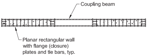
Figure description:
Image Analysis: CC-PSW/CF with planar rectangular C-PSW/CF
- Coupling beam: A central horizontal structural element connecting two wall sections.
- Planar rectangular walls: Located on either side of the coupling beam, consisting of:
- Flange (closure plates: Outer steel casing.
- Tie bars: Internal transverse reinforcement bars distributed throughout the wall sections.
- Concrete infill: Indicated by the stippled texture within the wall sections.
(a) CC-PSW/CF with planar rectangular C-PSW/CF
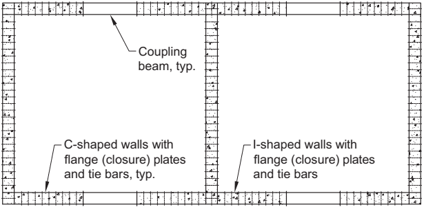
Figure description:
Structural Plan: CC-PSW/CF (Coupled Composite Plate Shear Walls / Concrete Filled
- Coupling Beams: Horizontal members connecting the main wall sections.
- C-shaped Walls: Perimeter wall components featuring flange (closure plates and internal tie bars.
- I-shaped Walls: Central vertical wall assembly also utilizing flange plates and tie bars.
- Internal Features: Concrete-filled wall sections reinforced with a grid of tie bars and closure plates.
(b) CC-PSW/CF with C-shaped and I-shaped C-PSW/CF
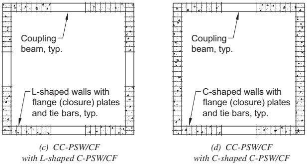
Figure description:
Key Information:
- Subject: Structural configurations of Coupled Composite Plate Shear Walls/Concrete Filled (CC-PSW/CF.
- Configuration (c: CC-PSW/CF using L-shaped wall segments.
- Configuration (d: CC-PSW/CF using C-shaped wall segments.
- Key Components:
- Coupling beams: Typical horizontal members connecting the wall segments.
- Wall Segments: Composite plate shear walls filled with concrete (C-PSW/CF.
- Structural Details: Both configurations feature flange (closure plates and tie bars within the wall cross-sections.
Fig. C-H8.1. CC-PSW/CF with different types of coupled C-PSW/CF.
H8.2 Basis of Design
The CC-PSW/CF system uses coupled walls to resist lateral loads, and it is expected to undergo significant inelastic deformation in large (design-basis and maximum considered) seismic events. The inelastic deformation has two sources: (a) flexural plastic hinges at the ends of coupling beams and (b) flexural yielding at the base of walls. The preferred inelastic failure mechanism consists of forming flexural plastic hinges at both ends of the coupling beams and at the base of the composite walls. The design implements a strong-wall/weak-coupling-beam approach that must be followed for appropriately sizing the composite members. This design approach helps achieve development of extensive plastic hinging in most of the coupling beams before significant yielding of the walls (Broberg et al., 2022).
H8.3 Analysis
The design approach put forward in this section leads to structures with the characteristic pushover behavior depicted in Figure C-H8.2. The initial branch represents the elastic behavior of the structure, and the slope of this branch represents the effective structural stiffness, which is approximated by elastic models such as those used with the Equivalent Lateral Force (ELF) procedure defined by ASCE/SEI 7. On the base shear-roof displacement curve, point A represents the lateral load level corresponding to the ELF distribution. The coupling beams are designed to reach their flexural capacity at this demand. As the lateral load and base shear force increases, the coupling beams along the height of the structure undergo flexural plastic hinging at both ends. The response reaches the next milestone, point B, where all the coupling beams have developed flexural hinges. The composite walls are designed to have a flexural capacity adequate to resist this demand level. The next milestone on the response, point C, corresponds to the overall inelastic mechanism with flexural plastic hinging in all the coupling beams and the base of the composite walls. A final milestone, point D, represents fracture failure of the composite walls. The overstrength factor for this system, defined as the ratio of ultimate load capacity to capacity at ELF level loads, is approximately the ratio of base shear force at point C to point A.
H8.3a Stiffness
The effective stiffness recommendations in Specification Section I1.5 for composite walls were verified by Agrawal et al. (2020) and Bruneau et al. (2019) for various archetype structure designs.
The flexural stiffness, , and axial stiffnesses, , of composite walls can also be calculated using cracked-transformed section properties corresponding to of the calculated nominal flexural capacity of the wall without accounting for axial force effects (Shafaei et al., 2021b). It is important to use the reduced, cracked section, axial stiffness of the walls because they have an influence on the structure lateral stiffness and story drift through the coupling frame action. The shear stiffness of the composite walls and coupling beams does not have a significant influence on the structure stiffness as flexure behavior dominates. As such, the uncracked composite shear stiffness can be used for both the coupling beams and composite walls.
H8.3c Required Strengths for Composite Walls
The design demands for the composite walls are estimated using a capacity-limited seismic load effect, , where all the coupling beams are assumed to develop plastic hinges at both ends with flexural capacity equal to , which occurs at point B in Figure C-H8.2 (Broberg et al., 2022). The total overturning moment at point B can be estimated using the total overturning moment at point A in Figure C-H8.2 amplified by the factor determined in Equation C-H8-1:
(C-H8-1)
where
The capacity-limited shear force in the coupling beams can be summed over the height of the structure to estimate the axial forces acting in the walls, , as shown in Equation C-H8-2.
(C-H8-2)
The portion of the total overturning moment resisted by coupling action can be estimated by the equal and opposite axial forces at the base of the walls, , multiplied by the distance between them. The remaining portion of the total overturning moment can be distributed to the individual walls based on their effective flexural stiffnesses,
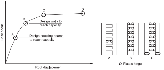
Figure description:
Structural Performance and Yielding Sequence of a Coupled Wall System
Base shear vs. Roof displacement
Legend
- Plastic hinge — color: Black outline; symbol: Open circle
Annotations
- Design coupling beams to reach capacity (text_label - position: Horizontal line extending right from Point A)
- Design walls to reach capacity (text_label - position: Horizontal line extending right from Point B)
| Point | Roof displacement (estimated units) | Base shear (estimated units) | Structural Response Stage |
|---|---|---|---|
| Origin | 0 | 0 | Elastic range |
| Intermediate | 8 | 30 | Near initial yielding |
| A | 15 | 45 | Initial yielding of coupling beams |
| Intermediate | 22 | 65 | Continued yielding of coupling beams |
| B | 30 | 75 | All coupling beams have reached capacity |
| Intermediate | 40 | 85 | Strain hardening before wall yielding |
| C | 50 | 90 | Formation of plastic hinges at wall bases |
| Intermediate | 75 | 93 | Plastic plateau |
| D | 100 | 95 | Ultimate capacity reached |
Notes: The figure consists of a pushover curve on the left and structural schematics on the right showing the progression of plastic hinge formation. Schematics A, B, and C correspond to points A, B, and C on the graph. In Schematic A, hinges form in several central coupling beams. In Schematic B, all coupling beams in the stack have developed hinges. In Schematic C, hinges exist in all coupling beams and have also formed at the bases of the structural walls. Point D marks the ultimate state of the system.
Fig. C-H8.2. Characteristic pushover (base shear-roof displacement) behavior.
accounting for the effects of tensile or compressive axial forces (Broberg et al., 2022; Shafaei et al., 2021b).
The shear force in the walls obtained from this analysis is amplified by a factor of 4 to conservatively account for (1) effects of higher modes, and (2) the overstrength in the walls resulting from the difference between their expected flexural capacities (at point C in Figure C-H8.2) and design demands (point B). For reinforced concrete walls, this amplification factor is about 2 to 3. A conservative value of 4 was used for composite walls in the absence of more complete information and in recognition of their inherent and significant shear strengths (Varma et al., 2022).
H8.4 Composite Wall Requirements
H8.4a Area of Steel Requirements
The area of steel requirements are based on the range of parameters included in research studies (Agrawal et al., 2020, Bruneau et al., 2019) and are similar to the requirements of the Specification.
H8.4b Steel Plate Slenderness Requirements
The steel plates are required to be nonslender; that is, yielding in compression occurs before local buckling. The plate slenderness limit was developed based on research conducted by Zhang et al. (2020).
H8.4c Tie Bar Spacing Requirements
The tie bar spacing requirement is the same as the one in the Specification. It is based on the flexibility and shear buckling of empty steel modules before concrete placement (Varma et al., 2019). Experimental and numerical results indicate that tie bars meeting the requirement of this provision provide adequate restraint for local buckling and concrete confinement in the composite phase (Agrawal et al., 2020; Harmon and Varma, 2021). Bhardwaj et al. (2018) indicate that modules that meet the plate slenderness requirement can typically be cast with concrete pour heights of up to 30 ft without significant influence of induced deflections and stresses on the compressive strength and buckling of the steel plates.
H8.4d Tie Bar-to-Plate Connection
This requirement develops the yield strength of the tie bars and enables yielding before failure of the tie bar-to-plate connection. Samples of tie bar-to-plate connection details are shown in Figure C-H8.3 for round tie bars.
H8.5 Composite Coupling Beam Requirements
H8.5a Minimum Area of Steel
The minimum area of steel requirement is based on the Specification Section I2 requirements for composite columns.
H8.5b Slenderness Requirements for Coupling Beams
The slenderness requirements are based on compact composite section requirements in Specification Section I1.4 for filled composite members. The web slenderness ratio requirement is based on developing the shear yield strength of the web plates before shear buckling in accordance with Specification Section G4. Figure C-H8.4 shows a schematic diagram of the coupling beam cross section along with the clear widths of the flange and web plates.
H8.5c Flexure-Critical Coupling Beams
The requirement in this section is based on achieving flexure-critical behavior in composite beams. The capacity-limited shear force capacity, , is increased by a factor of 1.2 to account for the effects of steel inelastic hardening in tension, concrete confinement, and the biaxial tensile stress effect in the steel tension flange (Varma et al., 2022).
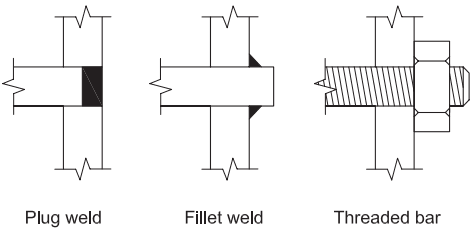
Figure description:
Fig. C-H8.3. Tie bar-to-plate connection detail samples
- Plug weld: The tie bar is secured within a hole in the plate using a weld that fills the recess.
- Fillet weld: The tie bar passes through the plate and is joined by fillet welds around its circumference on the exterior face.
- Threaded bar: A threaded tie bar passes through the plate and is secured externally with a nut.
Fig. C-H8.3. Tie bar-to-plate connection detail samples.
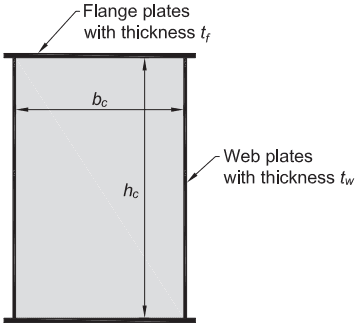
Figure description:
- Entity: Coupling beam section diagram.
- Flange plates: Located at the top and bottom with thickness .
- Web plates: Located on the sides with thickness .
- Dimensions:
- : Internal width between web plates.
- : Internal height between flange plates.
Fig. C-H8.4. Coupling beam section.
H8.6 Composite Wall Strength
The nominal tensile strength, compressive strength, flexural strength, combined axial force and flexural strength, and in-plane shear strength are based on the Specification recommendations for composite plate shear walls. The unsupported length for the flexural buckling of composite walls is typically equal to the story height.
H8.7 Composite Coupling Beam Strength
The nominal flexural strength and shear strength of composite coupling beams are based on the Specification recommendations for filled composite members.
H8.8 Coupling Beam-to-Wall Connections
The required flexural and shear strengths are calculated based on the expected flexural strengths of the coupling beams. The nominal flexural strength, with or without concurrent axial force, can be calculated using nominal steel and concrete material strengths. The expected flexural strength can be calculated using expected steel, , and concrete, , material strengths. The expected flexural strength, , of filled composite members is amplified by a factor of 1.2 to account for the effects of steel inelastic hardening in tension, concrete confinement, and the biaxial tensile stress effect in the steel tension flange. The coupling beam-to-wall connection is designed and detailed to resist this amplified flexural capacity of the beam, , and the associated capacity limited shear, .
H8.8c Rotation Capacity
As shown in Figure C-H8.5, these systems are intended to have a coupling beam-to-wall connection rotation capacity of at least 0.03 rad before degradation of beam flexural capacity due to fracture failure.
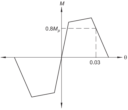
Figure description:
**Moment-Rotation Characteristic Curve for Structural Components Rendering Softening Behavior after Peak Strength is Reached at Specific Rotations (θ. Values for peak moment (M_peak, yield moment (M_yield, and ultimate rotation are visually estimated for completeness based on labeled reference points (0.03, 0.8M_p. behavior is symmetric about the origin (0,0. **
Moment-Rotation (M-θ Curve
Annotations
- 0.8M_p (text_label - position: y = 0.8M_p)
- 0.03 (text_label - position: x = 0.03)
- Point (0.03, 0.8M_p (text_label - position: (0.03, 0.8M_p)))
| Rotation (θ) | Moment (M) |
|---|---|
| -0.038 | 0 |
| -0.030 | -0.8M_p |
| -0.024 | -M_peak |
| -0.004 | -M_yield |
| 0.000 | 0 |
| 0.004 | M_yield |
| 0.024 | M_peak |
| 0.030 | 0.8M_p |
| 0.038 | 0 |
Fig. C-H8.5. Envelope of coupling beam end moment—chord rotation (M–θ).
H8.9 Composite Wall-to-Foundation Connections
For structures with subgrade basement stories, the maximum shear force and overturning moment in the composite walls at the grade level can be transferred gradually through the basement stories. For structures that are connected to the concrete basemat/foundation at the location of maximum shear force and overturning moment, the wall-to-basemat connections have to be designed for (a) the expected flexural capacity of the composite walls, accounting for effects of axial forces; (b) the expected axial forces associated with capacity-limited shear forces in the coupling beams; and (c) and the amplified shear force demand with an amplification factor of 4 used for the design of the composite walls.
H8.10 Protected Zones
For the CC-PSW/CF system, the protected zones are designated as the regions at the ends of coupling beams that will undergo significant inelastic straining and plastic hinging, as well as portions of the adjacent wall, if any, undergoing yielding at the connection. The typical length of the plastic hinge region will extend from the face of the composite wall to a distance equal to coupling beam depth. However, the extent of the plastic hinge and the protected zone can depend on the cross section geometry, the flange and web plate thicknesses, and the length-to-depth ratio of the coupling beam. The extent of the protected zone can be determined from analysis.
Additionally, the regions of the composite walls undergoing significant inelastic straining and plastic hinging are also designated as protected zones. The extent of the plastic hinge region undergoing significant inelastic strains and the protected zone can depend on wall cross-section geometry, web plate and flange (closure) plate thickness and length, and the height-to-length ratios of the walls. The extent of the protected zone can be determined from analysis.
The engineer can perform a rational analysis, such as an axial-moment-curvature analysis of the wall cross section and consider the bending moment (demand) diagram along the height of the wall to determine the region of inelastic straining in the steel and thus the protected zone. Typically, the portions of the wall height subjected to moments greater than of required flexural strength, , at the critical section in the region at the base of the wall can be considered as protected zones.
H8.11 Demand Critical Welds in Connections
Coupled composite wall systems include connections with several welded details as shown in Figure C-H8.6. These include (a) welds connecting the coupling beam flanges and web plates to composite wall steel plates, (b) welds connecting the coupling beam web plates to flange plates in built-up box sections, (c) welds in the composite wall steel plate splices, (d) welds connecting the composite wall flange (closure) plates to the web plates, and (e) welds at the composite wall steel plate-to-base plate connections.
Most of these welds can be designed and detailed appropriately for the required strengths, such that the weld stresses remain in the elastic range (Varma et al., 2022). Consequently, only the welds in the composite wall steel plate splices, when located in the protected zones, are designated as demand critical.
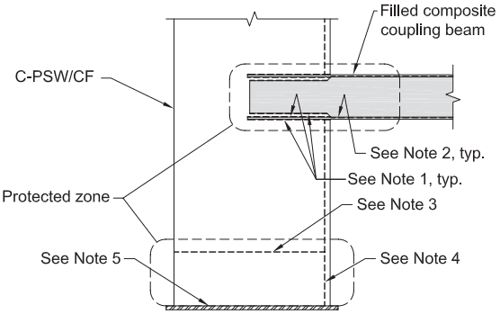
Figure description:
- C-PSW/CF: Main vertical structural composite plate shear wall.
- Filled composite coupling beam: Horizontal beam connected to the wall.
- Protected zones: Designated areas outlined by dashed lines at the beam-to-wall connection and the wall base.
- Note 1, typ.: Points to the welds connecting the coupling beam to the wall.
- Note 2, typ.: Points to the steel plates of the coupling beam.
- Note 3 & 4: Identify internal detailing/splices within the wall's base protected zone.
- Note 5: Points to the base plate connection of the composite wall.
Notes
- Welds connecting the coupling beam flanges and web plates to composite wall steel plates
- Welds connecting the coupling beam web plates to flange plates in built-up box sections
- Welds in the composite wall steel plate splices
- Welds connecting the composite wall flange (closure) plates to the web plates
- Welds at the composite wall steel plate-to-base plate connections
Fig. C-H8.6. Coupling beam-to-wall connection identifying critical welds