G3.1 Scope
Composite special moment frames (C-SMF) include a variety of configurations where steel or composite beams are combined with reinforced concrete or composite columns. In particular, composite frames with steel floor framing and composite or reinforced concrete columns have been used as a cost-effective alternative to frames with reinforced concrete floors (Griffis, 1992; Furlong, 1997; Viest et al., 1997).
G3.2 Basis of Design
Based on ASCE/SEI 7, C-SMF are permitted in all seismic design categories but are primarily intended for use in seismic design categories D, E, and F. Design and detailing provisions for C-SMF are comparable to those required for steel and reinforced concrete special moment frames and are intended to confine inelastic deformation to the beams and to the column bases. Because the inelastic behavior of C-SMF is comparable to that for steel or reinforced concrete SMF, the and values are the same as for those systems.
C-SMF are generally expected to experience significant inelastic deformation during a large seismic event. It is expected that most of the inelastic deformation will take place as rotation in beam “hinges” with limited inelastic deformation in the panel zone of the column. The beam-to-column connections for these frames are required to be qualified based on tests that demonstrate that the connection can sustain a story drift angle of at least 0.04 rad while maintaining a flexural resistance of at least 80% of the plastic moment of the composite beam, based on a specified loading protocol. Other provisions are intended to limit or prevent excessive panel-zone distortion, failure of connectivity plates or diaphragms, column hinging, and local buckling that may lead to inadequate frame performance in spite of good connection performance.
C-SMF and C-IMF connection configurations and design procedures are based on the results of qualifying tests; the configuration of connections in the prototype structure must be consistent with the tested configurations. Similarly, the design procedures used in the prototype connections must be consistent with tested configurations.
G3.4 System Requirements
G3.4a Moment Ratio
The strong-column weak-beam (SC/WB) mechanism implemented for composite frames is based on the similar concept for steel SMF. Refer to Commentary Section E3.4a for additional details and discussion. It is important to note that compliance with the SC/WB requirement and Equation G3-1 does not ensure that individual columns will not yield, even when all connection locations in the frame comply. However, yielding of beams will predominate, and the desired inelastic performance will be achieved in frames with members sized to meet the requirement of Equation G3-1.
Commentary Section E3.4a discusses the three exceptions to Equation E3-1. The same discussion applies here for Equation G3-1, with the exception that the axial force limit is , which is done to ensure ductile behavior of composite and reinforced concrete columns.
G3.4b Stability Bracing of Beams
For commentary on stability bracing of beams, see Commentary Section E3.4b.
G3.4c Stability Bracing at Beam-to-Column Connections
The stability bracing requirements at beam-to-column connections are similar to those for unbraced connections in steel SMF. Composite columns are typically not susceptible to flexural-torsional buckling modes due to the presence of concrete. The requirements of Section E3.4c.2 are applicable because composite columns are susceptible to flexural buckling modes in the out-of-plane direction.
G3.5 Members
G3.5a Basic Requirements
Reliable inelastic deformation for highly ductile members requires that width-to-thickness ratios be limited to a range that provides composite cross sections resistant to local buckling well into the inelastic range. Although the width-to-thickness ratio for compact elements in Specification Table I1.1 are sufficient to prevent local buckling before the onset of yielding, the available test data suggest that these limits are not adequate for the required inelastic deformations in C-SMF (Varma et al., 2002, 2004; Tort and Hajjar, 2004).
Encased composite columns classified as highly ductile members are required to meet the additional detailing requirements of Sections D1.4b.1 and D1.4b.2 to provide adequate ductility. For additional details, refer to Commentary Section D1.4b.
Filled composite columns are required to meet the additional requirements of Section D1.4c.
When the design of a composite beam satisfies Equation G3-2, the strain in the steel at the extreme fiber will be at least five times the tensile yield strain prior to concrete crushing at strain equal to 0.003. It is expected that this ductility limit will control the beam geometry only in extreme beam/slab proportions.
G3.5b Beam Flanges
For relevant commentary on changes in the cross section of beam flanges, see Commentary Section E3.5b.
G3.5c Protected Zones
For commentary on protected zones, see Commentary Section D1.3.
G3.6 Connections
While the Provisions permit the design of composite beams based solely upon the requirements in the Specification, the effects of reversed cyclic loading on the strength and stiffness of shear studs should be considered. This is particularly important for C-SMF, where the design loads are calculated assuming large member ductility and toughness. In the absence of test data to support specific requirements in the Provisions, the following special measures should be considered in C-SMF: (1) implementation of an inspection and quality assurance plan to verify proper welding of steel headed stud anchors to the beams (see Section A4.3 and Chapter J) and (2) use of additional steel headed stud anchors beyond those required in the Specification immediately adjacent to regions of the beams where plastic hinging is expected.
G3.6a Demand Critical Welds
For general commentary on demand critical welds, see Commentary Section A3.4.
G3.6b Beam-to-Column Connections
Connections to Reinforced Concrete Columns. A schematic connection drawing for composite moment frames with reinforced concrete columns is shown in Figure C-D2.10, where the steel beam runs continuously through the column and is spliced away from the beam-to-column connection. Often, a small steel column that is interrupted by the beam is used for erection and is later encased in the reinforced concrete column (Griffis, 1992). Numerous large-scale tests of this type of connection have been conducted in the United States and Japan under both monotonic and cyclic loading (Sheikh et al., 1989; Kanno and Deierlein, 1997; Nishiyama et al., 1990; Parra-Montesinos and Wight, 2000; Chou and Uang, 2002; Liang and Parra-Montesinos, 2004). The results of these tests show that carefully detailed connections can perform as well as seismically designed steel or reinforced concrete connections.
In particular, details such as the one shown in Figure C-D2.10 avoid the need for field welding of the beam flange at the critical beam-to-column junction. Therefore, these joints are generally not susceptible to the fracture behavior in the immediate connection region near the column. Tests have shown that of the many possible ways of strengthening the joint, face bearing plates as shown in Figure C-G3.1 and steel band plates as shown in Figure C-G3.2 attached to the beam are very effective for both mobilizing the joint shear strength of reinforced concrete and providing confinement to the concrete. Further information on design methods and equations for these composite connections is available in published guidelines (Nishiyama et al., 1990; Parra-Montesinos and Wight, 2001). Note that while the scope of the ASCE Guidelines (ASCE, 1994) limits their application to regions of low to moderate seismicity, test data indicate that the ASCE Guidelines are adequate for regions of high seismicity as well (Kanno and Deierlein, 1997; Nishiyama et al., 1990; Parra-Montesinos et al., 2003).
Connections to Encased Columns. Prior research has been conducted on the cyclic performance of encased columns and their connections (Kanno and Deierlein, 1997). Connections between steel beams and encased composite columns similar to those illustrated in Figure C-G3.1 have been used and tested extensively in Japan. Alternatively, the connection strength can be conservatively calculated as the strength of the connection of the steel beam to the steel column. Or, depending upon the joint
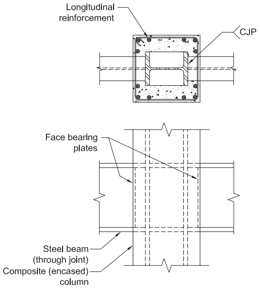
Figure description:
Fig. C-G3.1: Encased Composite Column-to-Steel Beam Moment Connection
Key Components and Labels:
- Composite (encased column: A structural member consisting of a steel H-section core encased in reinforced concrete.
- Steel beam (through joint: Continuous steel beams passing through the column joint.
- Longitudinal reinforcement: Vertical rebar positioned around the perimeter of the concrete encasement.
- Face bearing plates: Vertical plates situated at the interface of the beam and column to assist in load transfer.
- CJP: Complete Joint Penetration weld notation at the flange-to-column web connection.
- Transverse Reinforcement: Horizontal ties/hoops shown in the cross-section view surrounding the longitudinal bars.
Fig. C-G3.1. Encased composite column-to-steel beam moment connection.
proportions and detail, where appropriate, the strength can be calculated using an adaptation of design models for connections between steel beams and reinforced concrete columns (ASCE, 1994). One disadvantage of this connection detail compared to the one shown in Figure C-D2.10 is that, like standard steel construction, the detail in Figure C-G3.1 requires welding of the beam flange to the steel column.
Connections to Filled Columns. Research has also been conducted on the cyclic performance of filled columns and their connections, and there has been substantial research to support design strategies for connections similar to that shown in Figure C-G3.3 (Azizinamini and Schneider, 2004; Ricles et al., 2004a; Herrera et al., 2008). The results of these tests and the corresponding design details can be used to design the connections and prepare for the qualification according to Chapter K. For example, Figure C-G3.4 shows a large-scale filled composite column-to-steel beam connection that was tested by Ricles et al. (2004a) and demonstrated to exceed a story drift angle of 0.04 rad. In this same publication, the authors report test results for
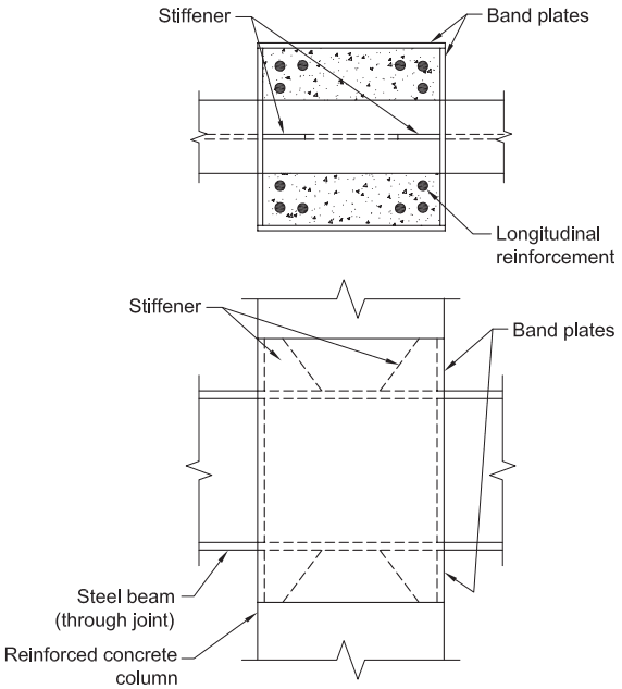
Figure description:
Key Entities and Details:
- Subject: Structural diagram of a reinforced concrete column-to-steel beam joint strengthened with steel band plates (Fig. C-G3.2.
- Components:
- Reinforced Concrete Column: The vertical structural member.
- Steel Beam: Passes through the joint horizontally.
- Band Plates: External steel plates wrapping the joint for reinforcement.
- Stiffeners: Internal plates used to reinforce the connection area.
- Longitudinal Reinforcement: Vertical rebar within the concrete column (visible in the top cross-section view.
- Views:
- Top View (Cross-section: Shows the arrangement of longitudinal reinforcement, internal stiffeners, and the outer band plates.
- Side Elevation: Shows the steel beam passing through the column, the vertical extent of the band plates, and the orientation of the stiffeners.
Fig. C-G3.2. Steel band plates used for strengthening the joint.
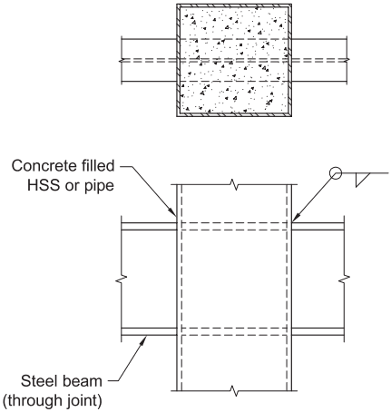
Figure description:
Subject: Filled composite column-to-steel beam moment connection.
Key Entities:
- Column: Concrete-filled Hollow Structural Section (HSS or pipe.
- Beam: Continuous steel beam passing through the joint ("through joint".
Key Details:
- Uninterrupted Flanges: Beam flanges pass continuously through the column.
- Welding: Fillet weld indicated at the interface of the beam and column shell.
- Configuration: The plan view depicts a square concrete-filled section; the elevation view shows the beam penetrating the column.
Fig. C-G3.3. Filled composite column-to-steel beam moment connection (beam flange uninterrupted).
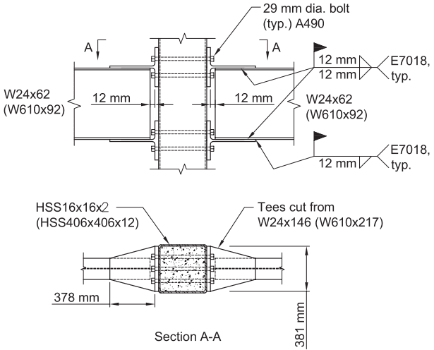
Figure description:
Connection Type: Filled composite column-to-steel beam moment connection (interrupted beam flange.
Key Components:
- Beams: W24x62 (W610x92 steel sections.
- Column: HSS16x16x1/2 (HSS406x406x12 filled with concrete.
- Connection Hardware: 29 mm diameter A490 bolts (typical.
- Structural Tees: Cut from W24x146 (W610x217 sections, used to connect beam flanges to the column.
Dimensions and Specifications:
- Bolted Connection Gap: 12 mm spacing at beam web/flange interface.
- Tee Length: 378 mm from column face.
- Section Width (A-A: 381 mm.
- Welding: 12 mm fillet welds, E7018 electrode (typical.
Fig. C-G3.4. Filled composite column-to-steel beam moment connection (beam flange interrupted) (Ricles, 2004a).
other large-scale filled composite column-to-beam connections that meet or exceed the story drift angle of 0.02 rad for C-IMF and 0.04 rad for C-SMF.
For the special case where the steel beam runs continuously through the composite column, as shown in Figure C-G3.2, the internal load transfer mechanisms and behavior of these connections are similar to those for connections to reinforced concrete columns. Otherwise, where the beam is interrupted at the column face, special details are needed to transfer the column flange loads through the connection (Azizinamini and Schneider, 2004).
G3.6c Conformance Demonstration
The Provisions require that connections in C-SMF meet the same story drift capacity of 0.04 rad as required for steel SMF. This section provides conformance demonstration requirements. This provision permits the use of connections qualified by prior tests or project specific tests. The engineer is responsible for substantiating conformance of the connection with the requirements.
For the special case where beams are uninterrupted or continuous through composite or reinforced concrete columns, and where beam flange welded joints are not used, the performance requirements are required to be demonstrated through large-scale testing in accordance with Section K2 or other substantiating data available in the literature (Kanno and Deierlein, 1997; Nishiyama et al., 1990; Parra-Montesinos and Wight, 2001; Parra-Montesinos et al., 2003).
G3.6d Required Shear Strength
The requirements for shear strength of the connection for C-SMF are comparable to those of SMF, with the exception that the calculation of the expected flexural strength must account for the different constituent materials. See Commentary Section E3.6d.
G3.6e Connection Diaphragm Plates
The requirements for diaphragm plates are the same for C-SMF as for C-IMF. Refer to Commentary Section G2.6e.
G3.6f Column Splices
The requirements for column splices are the same for C-SMF as for C-IMF. Refer to Commentary Section G2.6f.