In these Provisions, composite plate shear walls have been distinguished as being concrete encased (C-PSW/CE) in Section H6, concrete filled (C-PSW/CF) in Section H7, and coupled concrete filled (CC-PSW/CF) in Section H8. Both uncoupled systems covered in Sections H6 and H7 are designated as a single system, C-PSW in ASCE/SEI 7, Table 12.2-1 (ASCE, 2022). The coupled system covered in Section H8 is listed separately in ASCE/SEI 7, Table 12.2-1.
H7.1 Scope
C-PSW/CF are an alternative to reinforced concrete shear walls or special steel plate shear walls (SPSW), especially when relatively large seismic demand on the walls leads to dense reinforcement and large thicknesses in conventional concrete shear walls, or to relatively large wall thicknesses of the web infill and boundary elements in SPSW. C-PSW/CF can also be provided with filled hollow structural section (HSS) boundary elements in lieu of flange (closure) plates to address high seismic demands.
Examples of the types of wall cross-sections addressed by Section H7 are shown in Figure C-H7.1. These include planar walls with circular or half-circular boundary elements, planar walls with flange or closure plates, and C- or I-shaped walls with flange and web walls similar to planar walls. Previous editions of these Provisions permitted walls without any boundary elements. However, this edition of the Provisions does not permit the use of walls without any boundary elements, as recent studies (Agrawal et al., 2020) have shown that boundary elements enhance the seismic ductility of these systems.
The limits set forth in the scope are associated with the range of parameters considered in the investigations conducted on C-PSW/CF (Alzeni and Bruneau, 2014, 2017; Agrawal et al., 2020). The height-to-length ratio limit of 3 is based on the range of
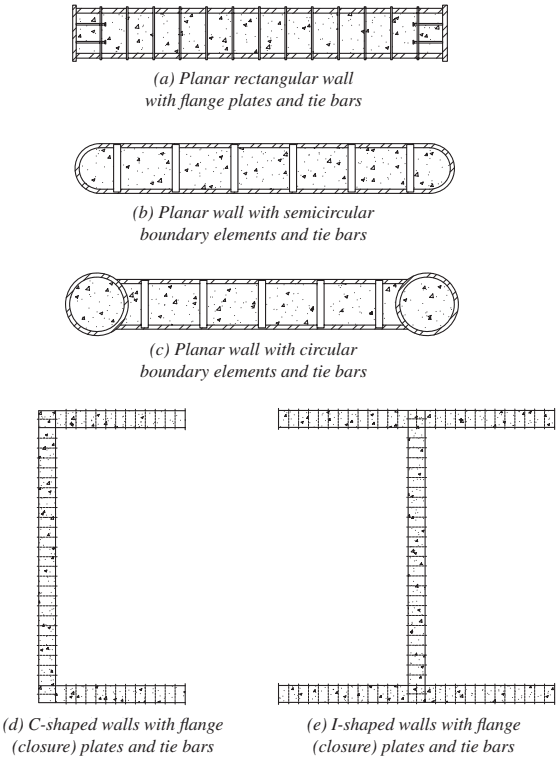
Figure description:
Key Information:
- Subject: Structural configurations of Concrete-Filled Composite Plate Shear Walls (C-PSW/CF with boundary elements or flange (closure plates.
- Common Components: All configurations consist of steel face plates, internal tie bars, and a concrete fill.
- Structural Types:
- (a Planar rectangular wall: Rectangular cross-section with flat flange plates at the ends.
- (b Planar wall with semicircular boundary elements: Planar wall with rounded, semicircular end caps.
- (c Planar wall with circular boundary elements: Planar wall terminating in full circular boundary columns.
- (d C-shaped walls: Flanged wall configuration forming a "C" profile using closure plates.
- (e I-shaped walls: Flanged wall configuration forming an "I" profile using closure plates.
Fig. C-H7.1. CPSW/CF with boundary elements or flange (closure) plates.
available test data for flexure-critical composite walls (Agrawal et al., 2020; Shafaei et al., 2021b).
H7.2 Basis of Design
Section H7 focuses on walls developing flexural hinging at the base. C-PSW/CF with boundary elements can develop flexural hinging with a strength equal to the wall cross-section plastic moment, . Past research (Alzeni and Bruneau, 2014, 2017; Agrawal et al., 2020; Shafaei et al., 2021b) has shown that the design of C-PSW/ CF having a height-to-length aspect ratio greater than 1.5 is governed by flexural strength; however, this can vary depending on the relative distribution of material between boundary elements and webs.
H7.3 Analysis
The effective stiffness recommendations for composite walls were verified by Agrawal et al. (2020) for various archetype structure designs.
H7.4 System Requirements for C-PSW/CF with Half-Circular or Circular Boundary Elements
H7.4a Steel Web Plate of C-PSW/CF with Half-Circular or Circular Boundary Elements
The maximum spacing of the tie bars is specified such that the steel plate can develop before local buckling. The specified limit has been validated experimentally.
H7.4b Half Circular or Circular Boundary Elements
The maximum slenderness of circular boundary elements is specified such that it can develop in compression before local buckling. The specified limit has been validated experimentally.
H7.4c Tie Bars
Tie bars serve to develop effective composite action in the sandwich panel. Tie bars provide shear transfer between the steel plate and the concrete core and are used to control local buckling of the web steel plates, as well as to prevent splitting of the concrete.
H7.5 System Requirements for C-PSW/CF with Flange or Closure Plates
H7.5a Steel Web and Flange Plates
The steel web and flange plates are required to be nonslender; that is, yielding in compression occurs before local buckling. The plate slenderness limit was developed based on research conducted by Zhang et al. (2014, 2020).
H7.5b Tie Bars
The tie bar spacing requirement is the same as the one in Specification Section I1.6b. It is based on the flexibility and shear buckling of empty steel modules before concrete placement, as discussed in detail in Varma et al. (2019). Experimental results indicate that tie bars meeting the requirement of this provision provide adequate restraint for local buckling and concrete confinement in the composite phase (Agrawal et al., 2020; Harmon and Varma, 2021).
H7.6 Members
H7.6a Flexural Strength
The available flexural strength of C-PSW/CF, , can be calculated using a plastic stress distribution over the wall cross section. This is in accordance with Specification Section I1.2a, where the steel yield stress in compression and tension is equal to and the concrete compressive stress is equal to . See Figure C-H7.2 for the assumed stress distribution in walls.
For C-PSW/CF with half-circular filled boundary elements
(C-H7-1)
\begin{aligned} & =0.5 A_{\mathrm{HSS}} F_{y, \mathrm{HSS}}\left(\frac{2 d_{\mathrm{HSS}}}{\pi}+b\right)+\left(b^{2}+2 C^{2}-2 C b\right) t_{s} F_{y, \text { web }} \\ & +\left(\frac{2 d_{i n}^{3}+3 \pi d_{i n}^{2} C+\frac{C^{2} t_{c}}{2}\right) f_{c}^{\prime}\end{aligned}}
where
(C-H7-2)
For C-PSW/CF with filled HSS boundary elements
(C-H7-3)
.
where
C = depth of cross section subjected to yield compressive stress, in. (mm) (C-H7-4)
specified minimum yield stress of the half-circular or full-circular end section, ksi (MPa)
specified minimum yield stress of the web, ksi (MPa)
(C-H7-5)
= depth of the steel web, in. (mm)
= diameter of the HSS section, in. (mm)
= specified compressive strength of concrete, ksi (MPa)
= thickness of concrete, in. (mm)
= thickness of steel plate, in. (mm)
H7.6b Shear Strength
The in-plane shear behavior is governed by the plane stress behavior of the steel plates and the orthotropic elastic behavior of concrete cracked in principal tension. The in-plane shear strength equations developed by Varma et al. (2014) and Seo et al. (2016) correspond to the limit state of von Mises yielding of the steel plates. The ultimate shear strength corresponds to the compression strut failure of the cracked concrete infill and can be substantially higher as discussed in Booth et al. (2020).
H7.7 Connection Requirements
H7.7a Connection between Tie Bars and Steel Plates
The full yielding force of the tie bar must be transferred to the steel plate. Examples of possible tie bar connections are shown in Figure C-H7.3. If plug welds are used to connect tie bars, the practicality of providing plug welds over at least half the steel plate thickness may lead to additional constraints on plate thickness or tie bar diameter.
H7.7b Connection between C-PSW/CF Steel Components
The welds between the steel web plates and the boundary elements, flange, or closure plates are detailed to develop the full yield strength of the connected plates.
H7.7c C-PSW/CF and Foundation Connection
To achieve capacity design principles, the flexural strength of the wall to be transferred to the foundation shall be computed considering expected strengths of the steel elements, expected strength of the concrete, and strain hardening of the steel. An overstrength factor of 1.1 is applied to the expected flexural strength of the wall to account for various effects, including strain hardening of the steel and confinement of the concrete. Application of the factor of 1.1 to the flexural capacity of the composite section instead of best reflects the section behavior observed in the supporting research (Agrawal et al., 2020). The engineer may consider higher values of the overstrength factor if appropriate for capacity design of such connections.
H7.8 Protected Zones
The extent of the protected zone cannot be prescribed to be limited to specific dimensions because the extent of yielding in a wall depends on the possible variations in (a) the geometry of the wall (height, length, C-shape, I-shape, etc.) and (b) material
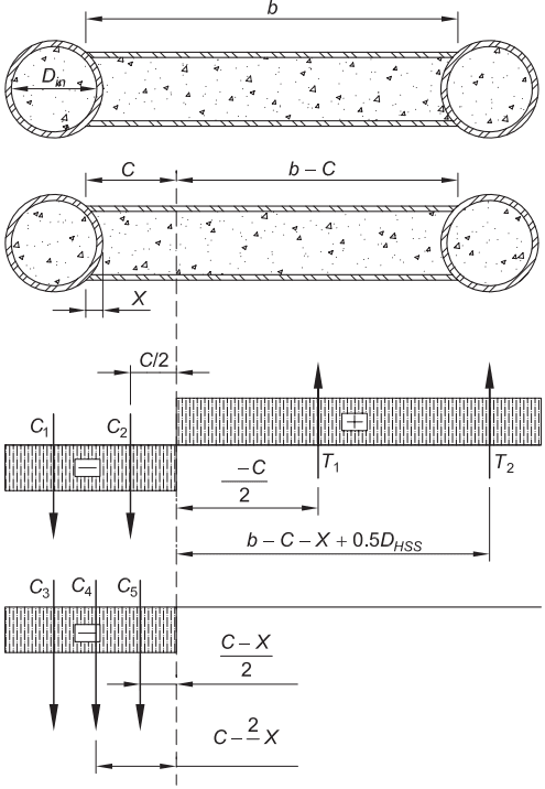
Figure description:
Key Information: Schematic Diagram of C-PSW/CF Stress Distribution
Subject: Schematic representation of stress distribution and internal resultant forces for a composite plate shear wall with concrete-filled (C-PSW/CF cross-sections.
Key Entities & Components:
- Cross-Section: A concrete-filled rectangular section bounded by two circular concrete-filled steel tubes.
- Internal Forces:
- Compression (: Resultant compressive forces acting on the concrete and steel on the left side of the neutral axis.
- Tension (: Resultant tensile forces acting on the steel on the right side of the neutral axis.
- Stress Blocks: Indicated by rectangular hatched areas marked with "−" for compression and "+" for tension.
Geometric Parameters:
- : Total width of the cross-section.
- : Inner diameter of the circular steel tubes.
- : Distance from the extreme compression fiber to the neutral axis.
- : Offset distance related to the tube wall geometry.
Key Mathematical Expressions for Force Arms:
- Tension side: and .
- Compression side: , , and (approximate from visual.
Fig. C-H7.2. Schematic diagram for stress distribution on C-PSW/CF cross section.
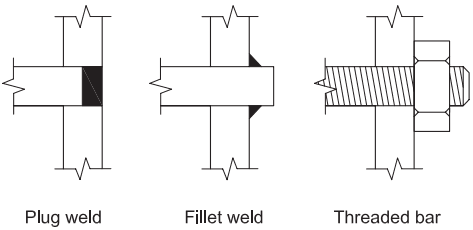
Figure description:
The image illustrates three examples of tie-to-plate connection details for C-PSW/CF cross sections:
- Plug weld: The tie is inserted into a hole in the plate and secured with a flush weld.
- Fillet weld: The tie passes through the plate and is secured with fillet welds at the interface.
- Threaded bar: A threaded tie bar passes through the plate and is secured with a nut.
Fig. C-H7.3 Examples of tie-to-plate connection detail.
properties (steel plate thickness, relationship between steel and concrete strengths used, yield stress, flange plates, etc.).
The engineer can perform a rational analysis, such as an axial-moment-curvature analysis of the wall cross section, and consider the bending moment (demand) diagram along the height of the wall to determine the region of inelastic straining in the steel and thus the protected zone. Typically, the portions of the wall height subjected to moments greater than of required flexural strength, , at the critical section in the region at the base of the wall can be considered as protected zones.