F5.1 Scope
In special plate shear walls (SPSW), the slender unstiffened steel plates (webs) connected to surrounding horizontal and vertical boundary elements (HBE and VBE) are designed to yield and behave in a ductile hysteretic manner during earthquakes. Figure C-F5.1 identifies the elements of SPSW. All HBE are rigidly connected to the VBE with moment-resisting connections able to develop the expected plastic moment of the HBE. Each web must be surrounded by boundary elements.
Experimental research on SPSW subjected to cyclic inelastic quasi-static and dynamic loading has demonstrated their ability to behave in a ductile manner and dissipate significant amounts of energy (Grondin and Behbahannidard, 2001; Zhao and Astaneh-Asl, 2004; Berman and Bruneau, 2005b; Sabouri-Ghomi et al., 2005; Sabelli and Bruneau, 2006; Deng et al., 2008; Li et al., 2010; Qu et al., 2008; Choi and Park,
2009; Qu and Bruneau, 2009; Vian et al., 2009b). This has been confirmed by analytical studies using finite element analysis and other analysis techniques (Sabelli and Bruneau, 2006; Dastfan and Driver, 2008; Bhowmick et al., 2009; Purba and Bruneau, 2009; Shishkin et al., 2009; Vian et al., 2009a; Qu and Bruneau, 2011; Purba and Bruneau, 2014a).
F5.2 Basis of Design
Yielding of the webs occurs by development of tension field action at an angle close to 45° from the vertical and buckling of the plate in the orthogonal direction. Past research shows that the sizing of VBE and HBE in a SPSW makes it possible to develop this tension field action across all of the webs. Except for cases with very stiff HBE and VBE, yielding in the webs develops in a progressive manner across each panel. Because the webs do not yield in compression, continued yielding upon repeated cycles of loading is contingent upon the SPSW being subjected to progressively larger drifts, except for the contribution of plastic hinging developing in the HBE to the total system hysteretic energy. In past research (Driver et al., 1997), the yielding of boundary elements contributed approximately 25 to 30% of the total
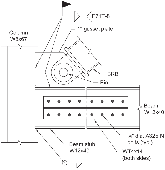
Figure description:
Fig. C-F4.6: Detail of Connection with Hinge
- Column: W8x67
- Beam & Beam Stub: W12x40
- Bracing: Buckling-Restrained Brace (BRB connected via a Pin
- Gusset Plate: 1" thick, secured with E71T-8 fillet welds to column and beam stub
- Splice Connection:
- WT4x14 members on both sides
- 3/4" diameter A325-N bolts (typical
Fig. C-F4.6. Detail of connection with hinge (Fahnestock et al., 2006).
strength of the system; however, that contribution will vary as a function of the web aspect ratio (Qu and Bruneau, 2009).
With the exception of plastic hinging at the ends of HBE, the surrounding HBE and VBE are designed to remain essentially elastic when the webs are fully yielded. Plastic hinging at the base of VBE, when VBE are connected to foundations in a way that makes it possible to develop their plastic moment, and at the ends of HBE are needed to develop the plastic collapse mechanism of this system. Plastic hinging within the span of HBE, which could partly prevent yielding of the webs, is undesirable as it can result in the following: (a) significant accumulation of plastic incremental deformations on the HBE, (b) partial yielding of the infill plates, (c) correspondingly lower global plastic strength, and (d) total (elastic and plastic) HBE rotations equal to twice the values that develop when in-span hinging is prevented (Purba and Bruneau, 2012). Some designers have used reduced beam section (RBS) connections at the ends of HBE to ensure that yielding occurs only at the RBS. Location and strength of RBS plastic hinges in HBE differ from those typically calculated for special moment frames (SMF), and these should be established using equations developed for this purpose (Qu and Bruneau, 2010b, 2011; Bruneau et al., 2011).
Cases of both desirable and undesirable yielding in VBE have been observed in past testing. In the absence of a theoretical formulation to quantify the conditions leading to acceptable yielding, and supporting experimental validation of this formulation, the conservative requirement of elastic VBE response is justified.
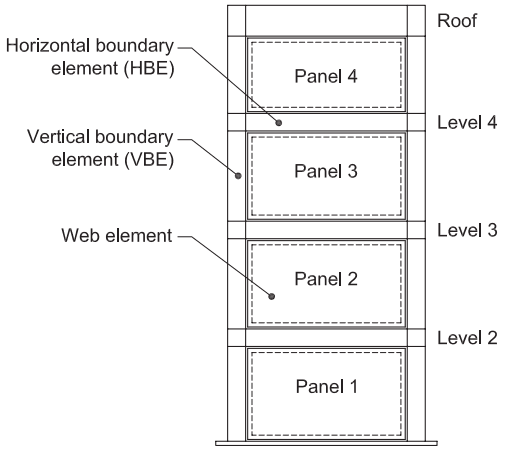
Figure description:
Special Plate Shear Wall (SPSW Schematic
- Vertical Boundary Elements (VBE: Vertical columns flanking the structure.
- Horizontal Boundary Elements (HBE: Horizontal beams at each floor and roof level.
- Web Elements (Panels: Four central infill plates, labeled Panel 1 through Panel 4 from bottom to top.
- Levels: Labeled from the base upwards as Level 2, Level 3, Level 4, and Roof.
Fig. C-F5.1. Schematic diagram of special plate shear wall.
Research literature often compares the behavior of SPSW to that of a vertical plate girder, indicating that the webs of an SPSW resist shears by tension field action and that the VBE of an SPSW resist overturning moments. While this analogy is useful in providing a conceptual understanding of the behavior of SPSW, many significant differences exist in the behavior and strength of the two systems. Past research shows that the use of structural shapes for the VBE and HBE in SPSW (as well as other dimensions and details germane to SPSW) favorably impacts orientation of the angle of development of the tension field action and makes possible the use of very slender webs having negligible diagonal compressive strength. Sizable top and bottom HBE are also required in the SPSW to anchor the significant tension fields that develop at the ends of the structural system. Limits imposed on the maximum web slenderness of plate girders to prevent flange buckling, or due to transportation requirements, are also not applicable to SPSW, which are constructed differently. For these reasons, the use of beam design provisions in the Specification for the design of SPSW is not appropriate (Berman and Bruneau, 2004).
F5.3 Analysis
Incremental dynamic analyses in compliance with FEMA P-695 procedures (FEMA, 2009b) have demonstrated that SPSW designed by distributing the applied story shear force between the webs and their boundary frame do not have a satisfactory margin of safety against collapse and have a high probability of developing excessive drifts (Purba and Bruneau, 2014a, 2014b, 2014c), contrary to SPSW having webs designed to resist the entire code-specified story shears.
An additional and unrelated requirement specifies that the strength of the frame consisting of VBE and HBE is at least 25% of the story shear force distributed to the SPSW. This requirement is intended to provide a minimum boundary frame to prevent excessive drifts, given that the boundary frame alone resists seismic forces until dynamic response excites the SPSW to drifts that exceed previously reached maximum values. Shake table tests by Dowden and Bruneau (2014) illustrated how SPSW with weak boundary frames can develop substantially greater drifts when subjected to identical earthquake excitations but after prior yielding of the infill plate. Although post-tensioned self-centering frames were used in that study, SPSW having weak boundary frames would behave similarly, but worse, without the benefit of selfcentering capabilities.
In accordance with capacity design principles, all edge HBE and VBE are designed to resist the maximum forces developed by the tension field action of the webs when fully yielded. Axial forces, shears, and moments develop in the boundary elements of the SPSW as a result of the response of the system to the overall overturning and shear, and the tension field action in the webs. Actual web thickness must be considered for this calculation because webs thicker than required may have to be used due to availability or minimum thickness required for welding. Where frames intersect, loading on the shared column should address the development of these forces in both frames.
At the top panel of the wall, the vertical components of the tension field should be anchored to the HBE. The HBE should have sufficient strength to allow development of full tensile yielding across the panel width.
Similarly, at the bottom panel of the wall, the vertical components of the tension field should also be anchored to the HBE. The HBE should have sufficient strength to allow development of full tensile yielding across the panel width. This may be accomplished by continuously anchoring the HBE to the foundation.
For intermediate HBE of the wall, the anticipated variation between the top and bottom web normal stresses acting on the HBE is usually small or null when webs in the panel above and below the HBE have identical thickness. Intermediate HBE are relatively small compared to the top and bottom HBE, which are typically of substantial size.
For the design of HBE, it may be important to recognize the effect of vertical stresses introduced by the tension field forces in reducing the plastic moment of the HBE. Concurrently, free-body diagrams of HBE should account for the additional shear and moments introduced by the eccentricity of the horizontal component of the ten sion fields acting at the top and bottom of the HBE (Qu and Bruneau, 2008, 2010b).
Forces and moments in the members and connections, including those resulting from tension field action, may be determined from a plane frame analysis. The web is represented by a series of inclined pin-ended strips, as described in Commentary Section F5.5b. A minimum of 10 equally spaced pin-ended strips per panel should be used in such an analysis.
A number of analytical approaches are possible to achieve capacity design and determine the same forces acting on the vertical boundary elements. Some example methods applicable to SPSW follow. In all cases, actual web thickness should be considered.
Nonlinear pushover analysis. A model of the SPSW can be constructed in which bilinear elasto-plastic web elements of strength are introduced at an angle . Bilinear plastic hinges can also be introduced at the ends of the horizontal boundary elements. Standard pushover analysis conducted with this model will provide axial forces, shears, and moments in the boundary frame when the webs develop yielding. Separate checks are required to verify that plastic hinges do not develop in the horizontal boundary elements, except at their ends.
Indirect capacity design approach. The Canadian Standards Association Limit States Design of Steel Structures (CSA, 2001), proposes that loads in the vertical boundary members can be determined from the gravity loads combined with the seismic loads increased by the amplification factor:
(C-F5-1)
where
- expected shear strength, at the base of the wall, determined for the web thickness supplied, kips (N)
- specified minimum yield stress of the web plate, ksi (MPa)
- distance between vertical boundary element centerlines, in. (mm)
- ratio of the expected yield stress to the specified minimum yield stress,
- required shear strength at the base of the wall, kips (N)
- = thickness of web plate, in. (mm)
- = angle of web yielding, as measured relative to the vertical, degrees
- force level adjustment factor
In determining the loads in VBE, the amplification factor, , need not be taken as greater than the seismic response modification coefficient, .
The VBE design axial forces are determined from overturning moments defined as follows:
- (a) The moment at the base is , where is the required overturning moment at the base of the wall corresponding to the force .
- (b) The moment extends for a height but not less than two stories from the base.
- (c) The moment decreases linearly above a height to times the overturning moment at one story below the top of the wall, but need not exceed times the required overturning moment at the story under consideration corresponding to the force .
The local bending moments in the VBE due to tension field action in the web should be multiplied by the amplification factor .
This method is capable of producing reasonable results for approximating VBE capacity design loads; however, as described previously, it can be unconservative as shown in Berman and Bruneau (2008a). This procedure relies on elastic analysis of a strip model (or equivalent) for the design seismic loads, followed by amplification of the resulting VBE moments by the factor . Therefore, it produces moment diagrams and SPSW deformations that are similar in shape to those obtained from a pushover analysis. Similarly, the determination of VBE axial forces from overturning calculations based on the design lateral loads amplified by results in axial force diagrams that are of the proper shape. However, following the above procedure, the amplification factor is found only for the first story and does not include the possibly significant strength of the surrounding frame. Based on the sizes of the HBE and VBE relative to the web for SPSW, the portion of the base shear carried by the surrounding moment frame can be substantial. As a result, estimates of VBE demands in accordance with this method are less than those required to develop full web yielding on all stories prior to development of hinges in VBE. In addition, in some cases, the ratio of web thickness provided to web thickness required for the design seismic loads can be larger on the upper stories than on the lower stories. In these situations, the indirect capacity design approach would underestimate the VBE design loads for the upper stories and capacity design would not be achieved. Neglecting these effects in the determination of will result in VBE design loads that are underestimated for true capacity design. Therefore, the full collapse mechanism should be used when determining the factor . Equation C-F5-15 in the following procedure is such an equation.
Combined Plastic and Linear Analysis. This procedure has been shown to give accurate VBE results compared to a pushover analysis (Berman and Bruneau, 2008a). Assuming that the web plates and HBE of an SPSW have been designed according to the Provisions to resist the factored loads (or, for the case of HBE design, the maximum of the factored loads or web plate yielding), the required capacity of VBE may be found from VBE free body diagrams, such as those shown in Figure C-F5.2 for a generic four-story SPSW. Those free body diagrams include distributed loads representing the web plate yielding at story and ; moments from plastic hinging of HBE, and ; axial forces from HBE, and ; applied lateral seismic load at each story to cause the plastic collapse mechanism, ; and base reactions
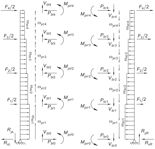
Figure description:
The image displays free body diagrams for the Vertical Boundary Elements (VBE of a four-story Special Plate Shear Wall (SPSW.
Key Entities and Forces:
- Lateral Seismic Loads (: Applied at each story level (1-4.
- Distributed Web Plate Yielding Loads:
- : Horizontal distributed loads acting on the VBE.
- : Vertical distributed loads acting along the VBE.
- HBE Interface Forces (Left and Right:
- Moments (: Plastic hinging moments from the Horizontal Boundary Elements.
- Axial Forces (: Forces transferred from the HBE.
- Shear Forces (: Vertical forces transferred from the HBE.
- Base Reactions:
- Left Support: Horizontal ( and vertical ( reactions.
- Right Support: Horizontal ( and vertical ( reactions.
Fig. C-F5.2. VBE free body diagrams.
for those lateral seismic loads, , and . Each of these loads can then be determined as follows:
- (1) The distributed loads to be applied to the VBE ( and ) and HBE ( and ) from plate yielding on each story, , may be determined as follows:
| ωyci = 0.5Fyptwi sin 2α | (C-F5-2) |
| ωxci = Fyptwi (sin α)² | (C-F5-3) |
| ωybi = Fyptwi (cos α)² | (C-F5-4) |
| ωxbi = 0.5Fyptwi sin 2α | (C-F5-5) |
where and are for the web-plate material and is the web thickness at level , respectively.
- (2) As part of estimating the axial load in the HBE, an elastic model of the VBE is developed as shown in Figure C-F5.3. The model consists of a continuous beam element representing the VBE that is pin-supported at the base and supported by elastic springs at the intermediate and top HBE locations. For HBE spring stiffnesses at each story can be taken as the axial stiffness of the HBE
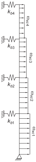
Figure description:
Elastic VBE model with HBE springs:
- Vertical Element: A multi-segmented vertical beam or boundary element.
- Support: A pinned support at the base of the vertical element.
- Lateral Springs: Four horizontal springs representing HBE (Horizontal Boundary Element stiffness, labeled through , connected to rigid supports.
- Distributed Loads: Four segments of horizontal distributed loads acting on the vertical element, labeled through .
- Configuration: The springs are located at the junctions between loading segments and at the top of the structure.
Fig. C-F5.3. Elastic VBE model with HBE springs.
considering one-half of the bay width (or HBE length for a considerably deep VBE), as exemplified in the following:
(C-F5-6)
where is the HBE cross-sectional area for story is the bay width, and is the modulus of elasticity. This VBE model is then loaded with the horizontal component of the forces from the web plates yielding over each story, namely, , and analysis returns spring forces, .
- (3) The axial force component in the intermediate and top HBE resulting from the horizontal component of the plate yield forces on the HBE, , is assumed to be distributed as shown in Figure C-F5.4. Note that for the bottom HBE, this distribution is the reverse of that in the top beam. These axial force components are then combined with the spring forces from the linear VBE model, resulting in the following equations for the axial force at the left and right sides of the intermediate and top HBE ( and , respectively):
(C-F5-7)
(C-F5-8)
where the spring forces, , should be negative, indicating that they are adding to the compression in HBE. As mentioned previously, the axial forces from and in the bottom HBE may be taken as the mirror image of those shown in Figure C-F5.4, where is zero in that particular case as there is no web below the bottom HBE. Furthermore, there are no spring forces to consider at the bottom HBE location as the horizontal component of force from web plate yielding on the lower portion of the bottom VBE is added to the base reaction determined as part of the plastic collapse mechanism analysis, as described in the following. Therefore, the bottom HBE axial forces on the right- and lefthand sides, and , are as follows:
(C-F5-9)
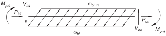
Figure description:
Entity: HBE Free Body Diagram (Fig. C-F5.4
- Structure: Horizontal beam element with a series of diagonal internal force arrows.
- Left End Forces/Moments:
- : Counter-clockwise moment.
- : Horizontal axial force (acting right.
- : Vertical shear force (acting down.
- Right End Forces/Moments:
- : Clockwise moment.
- : Horizontal axial force (acting right.
- : Vertical shear force (acting up.
- Distributed Load/Parameters:
- : Top edge parameter.
- : Bottom edge parameter.
Fig. C-F5.4. HBE free body diagram.
(C-F5-10)
- (4) The reduced plastic moment capacity at the HBE ends can be approximated by the following:
(a) When
(C-F5-11)
(b) When
(C-F5-12)
where is the HBE expected yield strength multiplied by 1.1 to account for some strain hardening, is the HBE cross-sectional area for story , and is the HBE plastic section modulus for story .
- (5) The shear forces at the left and right ends of all HBE, and , can be found from the following:
(C-F5-13)
(C-F5-14)
- (6) The applied loads for the SPSW collapse mechanism can be found from the following:
(C-F5-15)
where is the applied lateral seismic load at each story to cause the plastic col- lapse mechanism and is the height from the base to each story. Note that the indices for the HBE plastic moment summations begin at zero so that the bottom HBE (denoted ) is included. To employ Equation C-F5-15 in calculating the applied lateral loads that cause this mechanism to form, it is necessary to assume some distribution of those loads over the height of the structure—that is, a relationship between , etc. For this purpose, a pattern equal to that of the design lateral seismic loads from the appropriate building code may be used.
- (7) Horizontal reactions at the column bases, and , are then determined by dividing the collapse base shear by 2 and adding the pin-support reaction from the VBE model, , to the reaction under the left VBE and subtracting it off the reaction under the right VBE. Vertical base reactions can be estimated from overturning calculations using the collapse loads as follows:
(C-F5-16)
- (8) The moment, axial, and shear force diagrams for the VBE are established once all the components of the VBE free body diagrams are estimated. The diagrams give minimum design actions for the VBE such that they can resist full web plate yielding and HBE hinging.
VBE should be designed to remain elastic under the large shears resulting from this analysis. Existing literature shows instances of undesirable inelastic behavior when shear yielding occurred in the VBE (Qu and Bruneau, 2008, 2010a).
Preliminary Design. For preliminary proportioning of HBE, VBE, and webs, the wall may be approximated by a vertical truss with tension diagonals. Each web is represented by a single diagonal tension brace within the story. For an assumed angle of inclination of the tension field, the web thickness, , may be taken as
(C-F5-17)
where
- = area of the equivalent tension brace, in.
- = distance between VBE centerlines, in. (mm)
- = angle between the vertical and the longitudinal axis of the equivalent diagonal brace, degrees
- = assumed angle of inclination of the tension field measured from the vertical in accordance with Section F5.5a
- system overstrength factor, as defined by FEMA 369 (FEMA, 2001), and taken as 1.2 for SPSW (Berman and Bruneau, 2003b)
A is initially estimated from an equivalent brace size to meet the structure's drift requirements.
F5.4 System Requirements
Panel Aspect Ratio. The 2005 Provisions for the design of SPSW limited their applicability to wall panels having aspect ratios of . This limit was first introduced in the 2003 edition of the NEHRP Recommended Provisions for Seismic Regulations for New Buildings and Other Structures (FEMA 450) (FEMA, 2003), as a most conservative measure in light of the relatively limited experience with that structural system in the United States at the time. Since then, SPSW designed in compliance with the Provisions and having lower aspect ratios have been observed to perform satisfactorily. For example, SPSW specimens having of 0.6 (Li et al., 2010) exhibited ductile hysteretic behavior comparable to that of walls with larger aspect ratios.
No theoretical upper bound exists on , but as the SPSW aspect ratio increases, progressively larger HBE will be required, driven by the capacity design principles embodied in the design requirements. This will create a de facto practical limit beyond which SPSW design will become uneconomical and impractical, and no arbitrary limit needs to be specified provided the engineer ensures that all strips yield at the target drift response (Bruneau and Bhagwagar, 2002).
Past research has focused on walls with an ratio ranging from 300 to 800 . Although no theoretical upper bound exists on this ratio, drift limits will indirectly constrain this ratio. The requirement that webs be slender provides a lower bound on this ratio. For these reasons, no limits are specified on the ratio.
F5.4a Stiffness of Boundary Elements
The stiffness requirement was originally intended to prevent excessive in-plane flexibility and buckling of VBE. However, subsequent research showed that the specified limits on stiffness were uncorrelated to satisfactory in-plane and out-of-plane VBE performance and that stiffer boundary elements principally served to ensure full yielding of the webs at smaller drifts (Qu and Bruneau, 2010a). It was also experimentally demonstrated that SPSW having VBE stiffness exceeding these prescribed limits could perform satisfactorily (Li et al., 2010). The stiffness limits provided in Section F5.4a can be expected to result in boundary elements with adequate stiffness to develop full yielding of the webs at the design drift. The engineer may also demonstrate by other methods, such as pushover analysis, that this design objective is attained.
F5.4c Bracing
Providing stability of SPSW system boundary elements is necessary for proper performance of the system. Past experience has shown that SPSW can behave in a ductile manner with beam-to-column connections detailed in accordance with intermediate moment frame requirements. As such, lateral bracing requirements are specified to meet the requirements for moderately ductile members. In addition, all intersections of HBE and VBE must be braced to ensure stability of the entire panel.
F5.4d Openings in Webs
Large openings in webs create significant local demands and thus must have HBE and VBE in a similar fashion as the remainder of the system. When openings are required, SPSW can be subdivided into smaller SPSW segments by using HBE and VBE bordering the openings. With the exception of the structural systems described in Section F5.7, SPSW with holes in the web not surrounded by HBE and VBE have not been tested. The Provisions allow openings without boundary elements if justified by analysis or testing.
F5.5 Members
F5.5a Basic Requirements
Some amount of local yielding is expected in the HBE and VBE to allow the development of the plastic mechanism of SPSW systems. For that reason, HBE and VBE must comply with the requirements for highly ductile members in Table D1.1, as required for SMF.
F5.5b Webs
The lateral shears are carried by tension fields that develop in the webs stressing in the direction , defined in this Section. When the HBE and VBE of a web are not identical, the average of HBE areas may be taken in the calculation of , and the average of VBE areas and moment of inertias may be respectively used in the calculation of and to determine .
Dastfan and Driver (2008) demonstrated that the strength of SPSW designed in compliance with current requirements is not substantially sensitive to the angle of inclination of the strips. The orientation of the post-buckling principal stresses that develop in the infill plates of SPSW vary in a complex manner as a function of drift and location along boundary elements. Pushover analyses of nonlinear finite elements models can capture these variations, but it is not a practical tool for design. The strip model simplifies this complex behavior of SPSW in a manner suitable for design. Previous editions of these Provisions provided an equation to determine the angle to be used in the strip model, derived considering the relative elastic flexibility of boundary elements surrounding a single panel, but that equation provided a disproportionate sense of accuracy and results that did not recognize the variations as a function of drift, geometry, and progressive inelasticity observed in actual behavior. Studies by Shishkin et al. (2005), Moghimi and Driver (2014a, 2014b), Webster et al. (2014), Fu et al. (2017), and Fu and Bruneau (2019) showed that the inclination angle used for the tension strips had little impact on the predicted ultimate strength of an SPSW for angles ranging from to ; therefore, an angle of is recommended.
The plastic shear strength of panels is given by . The nominal strength is obtained by dividing this value by a system overstrength, as defined by FEMA 369 (FEMA, 2001), and taken as 1.2 for SPSW (Berman and Bruneau, 2003b).
The plastic shear strength is obtained from the assumption that, for purposes of analysis, each web may be modeled by a series of equally spaced inclined pin-ended strips, oriented at angle as shown in Figure C-F5.5. Past research has shown that this model provides realistic results, as shown in Figure C-F5.6 for example, provided that at least 10 equally spaced strips are used to model each panel.
F5.5c HBE
Purba and Bruneau (2012, 2014a) demonstrated that plastic hinging within the span of HBE can produce excessive accumulation of plastic incremental deformations on the HBE, as well as partial yielding of the infill plates and correspondingly lower
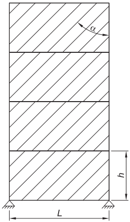
Figure description:
Key Information:
- Subject: Strip model representation of a four-story Special Plate Shear Wall (SPSW.
- Structural Elements: Four vertically stacked rectangular panels featuring parallel diagonal lines representing tension strips.
- Parameters:
- L: Panel width.
- h: Story height.
- α (alpha: Angle of the tension strips relative to the vertical boundary.
- Support: Pin supports are indicated at the base of the structure.
Fig. C-F5.5. Strip model of an SPSW.
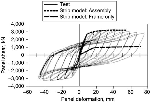
Figure description:
Cyclic Load-Deformation Plot
Legend
- Test — color: Grey; symbol: Solid thin line
- Strip model: Assembly — color: Black; symbol: Thick dotted line
- Strip model: Frame only — color: Black; symbol: Thick dashed line
| Panel deformation, mm | Strip model: Assembly (kN) | Strip model: Frame only (kN) | Test Envelope (kN) |
|---|---|---|---|
| -48 | null | null | -3000 |
| -35 | null | null | -3100 |
| -24 | null | null | -2800 |
| -12 | null | null | -1800 |
| -10 | null | null | -1500 |
| 0 | 0 | 0 | 0 |
| 2 | 500 | null | null |
| 4 | 1000 | null | null |
| 5 | null | 250 | null |
| 6 | 1700 | null | null |
| 8 | 2400 | null | null |
| 10 | 2700 | 500 | null |
| 12 | null | null | 1800 |
| 15 | 2950 | 800 | null |
| 18 | null | 1000 | null |
| 20 | 3100 | null | null |
| 22 | null | null | 2900 |
| 30 | 3200 | 1050 | null |
| 34 | null | null | 3200 |
| 40 | 3200 | null | null |
| 45 | null | null | 3100 |
| 50 | 3200 | 1100 | null |
| 55 | 3200 | null | null |
| 58 | null | null | 2900 |
| 70 | null | 1150 | null |
| 75 | null | null | 2700 |
Notes: The chart shows the cyclic response (hysteresis loops for the 'Test' data and the monotonic backbone curves for the two strip models. The data points in the table for 'Test Envelope' represent the peak values of the experimental hysteresis loops.)
Fig. C-F5.6. Comparison of experimental results for lower panel of multistory SPSW frame and strength predicted by strip model (Driver et al., 1997).
global plastic strength. This section offers two design approaches to prevent in-span HBE plastic hinges:
(1) Provide an HBE plastic section modulus equal to (C-F5-18)
where and are HBE span and yield stress, respectively, and is the vertical component of infill plate stress, defined as
(C-F5-19)
where and are the infill plate yield stress and the infill thickness, respectively, and is the tension field inclination angle. This is equivalent to designing the HBE to resist a moment equal to .
- (2) Use RBS at the ends of HBE to ensure plastic hinging develops only at the RBS. Note that location and strength of RBS plastic hinges in HBE differ from those typically calculated for special moment frames, and these should be established using equations developed for this purpose (Qu and Bruneau, 2010b, 2011; Bruneau et al., 2011).
Further details on these two design approaches are provided in Vian and Bruneau (2005).
F5.5d Protected Zones
Parts of SPSW expected to develop large inelastic deformations, and their connections, are designated as protected zones to meet the requirements of Section D1.3.
F5.6 Connections
F5.6a Demand Critical Welds
Demand critical welds are required in accordance with Section A3.4b consistent with similar requirements for all seismic force-resisting systems.
F5.6b HBE-to-VBE Connections
Due to the large initial stiffness of SPSW, total system drift and plastic hinge rotation demands at the ends of HBE are anticipated to be smaller than for special moment frames. The requirements of Section E2.6b for IMF are deemed adequate for HBE-to-VBE connections.
F5.6b.1 Required Strength
Connections of the HBE to VBE are designed to develop the plastic strength of the HBE given that plastic hinging is expected at the ends of HBE.
F5.6b.2 Panel Zones
Panel-zone requirements are not imposed for intermediate HBE where generally small HBE connect to sizable VBE. The engineer should use judgment to identify special situations in which the panel-zone adequacy of VBE next to intermediate HBE should be verified.
F5.6c Connections of Webs to Boundary Elements
Web connections to the surrounding HBE and VBE are required to develop the expected tensile strength of the webs. Net sections must also provide this strength for the case of bolted connections.
The strip model can be used to model the behavior of SPSW and the tensile yielding of the webs at angle, . A single angle of inclination taken as the average for all the panels may be used to analyze the entire wall. The expected tensile strength of the web strips are defined as ,
where
of a strip, in.
- width of panel, in. (mm)
- height of panel, in. (mm)
- = number of strips per panel; taken greater than or equal to 10
This analysis method has been shown, through correlation with physical test data, to adequately predict SPSW performance. It is recognized, however, that other advanced analytical techniques, such as the finite element method (FEM), may also be used for design of SPSW. If such nonlinear (geometric and material) FEM models are used, they should be calibrated against published test results to ascertain reliability for application. Designs of connections of webs to boundary elements should also anticipate buckling of the web plate. Some minimum out-of-plane rotational restraint of the plate should be provided (Caccese et al., 1993).
F5.6d Column Splices
The importance of ensuring satisfactory performance of column splices is described in Commentary Section D2.5.
F5.7 Perforated Webs
F5.7a Regular Layout of Circular Perforations
Special perforated steel plate walls (SPSPW) are a special case of SPSW in which a special panel perforations layout is used to allow utilities to pass through and that may be used to reduce the strength and stiffness of a solid panel wall to levels required in a design when a thinner plate is unavailable. This concept has been analytically and experimentally proven to be effective, and the system remains ductile up to the drift demands corresponding to severe earthquakes (Vian and Bruneau, 2005; Vian et al., 2009a, 2009b; Purba and Bruneau, 2007). A typical hole layout for this system is shown in Figure C-F5.7 for a case having four horizontal lines of holes and seven vertical lines of holes. The design equations provided in Section F5.7a have been validated for webs having at least four horizontal and vertical lines of holes.
Note that while general equations could be derived for lines of holes aligned at any angle from the horizontal, Equation F5-2 is applicable only to the special case of holes that align diagonally at 45° from the horizontal because it was deemed to be the simplest and most practical configuration and because it is the only orientation that has been considered while developing Equation F5-2 (Purba and Bruneau, 2007). As shown in Figure C-F5.7, perforating webs in accordance with this section result in the development of web yielding in a direction parallel to that of the holes alignment.
Designing SPSW in low- to medium-rise buildings using hot-rolled steel often results in required panel thicknesses less than the minimum plate thickness available from steel producers. In such cases, using the minimum available thickness would result in large panel force overstrength, proportionally larger design demands on the surrounding VBE and HBE, and an overall less economical system. Attempts at alleviating this problem were addressed by the use of light-gage, cold-formed steel panels (Berman and Bruneau, 2003a, 2005b). SPSPW instead reduce the strength of the web by adding to it a regular grid of perforations. This solution simultaneously helps address the practical concern of utility placement across SPSW. In a regular SPSW, the infill panel that occupies an entire frame bay between adjacent HBE and VBE is a protected element, and utilities that may have otherwise passed through at that location must either be diverted to another bay or pass through an opening surrounded by HBE and VBE. This either results in additional materials for the extra stiffening or in additional labor for the relocation of ductwork in a retrofit, for example. SPSPW provide a more economical alternative.
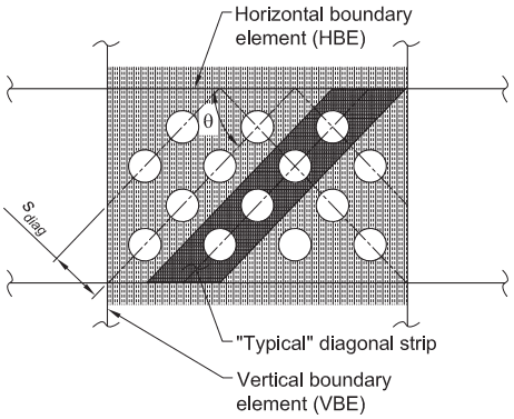
Figure description:
- Entity: Special Perforated Steel Plate Wall (SPSPW
- Key Components:
- Horizontal Boundary Element (HBE: Horizontal framing members at the top and bottom.
- Vertical Boundary Element (VBE: Vertical framing members on the sides.
- Perforated Plate: Central web with a regular grid of circular openings.
- "Typical" Diagonal Strip: A highlighted shaded section representing the tension field action path between perforations.
- Geometric Parameters:
- : Angle of the diagonal tension strip relative to the vertical.
- : Spacing between the centerlines of the diagonal strips.
Fig. C-F5.7. Schematic detail of special perforated steel plate wall and typical diagonal strip.
F5.7b Reinforced Corner Cut-Out
It is also possible to allow utility passage through a reinforced cutout designed to transmit the web forces to the boundary frame. While providing utility access, this proposed system provides strength and stiffness similar to a solid panel SPSW system. The openings are located immediately adjacent to the column in each of the top corners of the panel, a location where large utilities are often located. A cut-out radius as large as 19.6 in. (490 mm) for a half-scale specimen having a 6.5 ft (2 m) center-to-center distance between HBE has been successfully verified experimentally and analytically by Vian and Bruneau (2005) and Purba and Bruneau (2007).
Forces acting in the reinforcing arch, the curved plate at the edge of the opening, are a combination of effects due to arching action under tension forces due to web yielding and thrusting action due to change of angle at the corner of the SPSW, as illustrated in Figures C-F5.8 and C-F5.9. The latter is used to calculate the required maximum thickness of the “opening” corner arch at the top left side of Figure C-F5.8, with no web stresses assumed to be acting on it. The arch plate width is not a parameter that enters the solution of the interaction equation in that calculation, and it is instead conservatively obtained by considering the strength required to resist the axial component of force in the arch due to the panel forces at the closing corner, top right side of Figure C-F5.8. Because the components of arch forces due to panel forces are opposing those due to frame corner opening as shown in Figure C-F5.9, the actual forces acting in the arch plate will be smaller than the forces calculated by considering the components individually as is done previously for design.
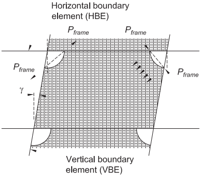
Figure description:
Key Information: Diagram of Arch End Reactions in a Reinforced Cut-out Corner (Steel Plate Shear Wall
-
Main Components:
- Horizontal Boundary Element (HBE: Top and bottom horizontal frame members.
- Vertical Boundary Element (VBE: Side vertical frame members.
- Infill Panel: Central section with vertical dashed lines representing the tension field.
- Reinforcing Arches: Curved plate segments at the corners of the panel openings.
-
Key Force Parameters:
- : Represents reactions and forces due to frame deformations at the corners.
- : Indicates the shear angle/drift of the frame deformation.
- Tension Field: Illustrated by dashed vertical lines, exerting forces on the arch plates.
-
Observed Behaviors:
- Corner Opening (Top Left: The arch is subject to thrusting action due to the change in corner angle.
- Corner Closing (Top Right: Arch forces are determined by resisting the axial component of forces from the infill panel.
- Force Interaction: Arch forces due to frame deformation oppose those due to panel forces.
Fig. C-F5.8. Arch end reactions due to frame deformations and infill panel forces on arches due to tension field action on reinforced cut-out corner.
Note that when a plate in the plane is added to the reinforcement arch to facilitate infill panel attachment to the arch in the field, it results in a stiffer arch section that could, due to compatibility of frame corner deformation, partly yield at large drifts. However, Vian and Bruneau (2005) and Purba and Bruneau (2007) showed that the thickness of the flat plate selected in accordance with the above procedure is robust enough to withstand the loads alone, and that the presence of the stiffer and stronger T-section (due to the attachment plate) is not detrimental to the system performance.
Based on this discussion, the nominal axial strength of the arching plate in compression or tension may be taken as , and the nominal flexural strength of the arching plate may be taken as ,
where
- specified minimum yield stress of the arching plate, ksi (MPa)
- cross-sectional area of the arching plate, in.
Where the arching plate is subjected to combined axial compression and flexural forces, the following interaction equation may be used:
(C-F5-20)
Nonlinear static pushover analysis is a tool that can be used to confirm that the selected reinforcement section will not produce an undesirable “knee-brace effect” or precipitate column yielding or beam yielding outside of the hinge region.
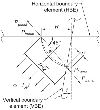
Figure description:
Key Information:
- Entities:
- Horizontal Boundary Element (HBE: The top horizontal structural member.
- Vertical Boundary Element (VBE: The side structural member, shown at a tilt angle .
- Right Arch: A curved structural component connecting the HBE and VBE, depicted in both original and deformed states.
- Forces and Loads:
- and : Concentrated forces acting at the boundary connection points.
- : Distributed load acting along the arch.
- Geometric Parameters:
- : Horizontal radius/span.
- : Diagonal chord length.
- : Angle of the diagonal chord relative to the HBE.
- : Eccentricity or rise of the arch deformation.
- : Displacement/deformation at the VBE connection.
- Context: The diagram illustrates the deformed configurations and forces used in nonlinear static pushover analysis to evaluate reinforcement and avoid undesirable yielding effects.
Fig. C-F5.9. Deformed configurations and forces acting on right arch.