Prior to the 2016 edition of these Provisions, composite plate shear walls (C-PSW) were included in a single section. Since then, they have been treated as distinct systems, composite plate shear walls-concrete encased (C-PSW/CE) in Section H6 and composite plate shear walls-concrete filled (C-PSW/CF) in Section H7. Both of these systems are designated as a single system, C-PSW, in ASCE/SEI 7, Table 12.2-1 (ASCE, 2022).
H6.1 Scope
C-PSW/CE can be used most effectively where story shear loads are large and the required thickness of conventionally reinforced shear walls is excessive. Limited research on these types of systems has included configurations in which reinforced concrete is used on one side of the steel plate to mitigate the effects of local buckling (Zhao and Astaneh-Asl, 2004) and cases where two steel plates are used with reinforced concrete between them (Ozaki et al., 2004), as covered in Section H7.
H6.3 Analysis
H6.3a Webs
In keeping with the intended system response, the provisions of this section target having the steel webs of the C-PSW/CE system be the primary structural elements that first attain inelastic response.
H6.3b Other Members and Connections
The provisions of this section intend to have the boundary elements of the C-PSW/ CE system remain essentially elastic under the maximum forces that can be generated by the fully yielded steel webs, along with the engaged portions of the reinforced concrete webs after the steel webs have fully yielded, except that plastic hinging at the ends of horizontal boundary elements (HBE) and the column base are permitted.
H6.4 System Requirements
The provisions of Section F5 are invoked in Sections H6.4b and H6.4c so that the boundary elements have adequate stiffness and strength.
H6.4e Openings in Webs
Careful consideration should be given to the shear and flexural strength of wall piers and of spandrels adjacent to openings. In particular, composite walls with large door openings may require structural steel boundary members attached to steel plates around the openings.
H6.5 Members
H6.5b Webs
The Provisions limit the shear strength of the wall to the yield strength of the plate because there is an insufficient basis from which to develop design rules for combining the yield strength of the steel plate and the shear strength of the reinforced concrete panel. Moreover, because the shear strength of the steel plate usually is much greater than that of the reinforced concrete encasement, neglecting the contribution of the concrete does not have a significant practical impact. ASCE/SEI 7 assigns structures with composite walls a slightly higher value than special reinforced concrete walls because the shear yielding mechanism of the steel plate will result in more stable hysteretic loops than for reinforced concrete walls.
H6.5c Concrete Stiffening Elements
Minimum reinforcement in the concrete cover is required to maintain the integrity of the wall under reversed cyclic in-plane and out-of-plane loading. Consideration should be given to splitting of the concrete element on a plane parallel to the steel plate. Until further research data are available, the minimum required wall reinforcement is based upon the specified minimum value for reinforced concrete walls in ACI 318 (ACI, 2019). Examples of such reinforcement are shown in Figures C-H6.1 and C-H6.2.
H6.5d Boundary Members
C-PSW/CE systems can develop significant diagonal compression struts, particularly if the concrete is activated directly at the design earthquake displacement. These Provisions ensure that the boundary elements have adequate strength to resist this force.
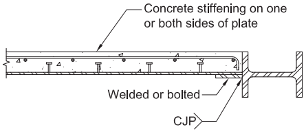
Figure description:
Figure C-H6.1: Concrete stiffened steel shear wall with steel boundary member
- Concrete Stiffening: Applied to one or both sides of the steel plate; includes internal reinforcement bars and shear studs.
- Steel Boundary Member: An H-shaped or I-shaped steel section connected to the wall assembly.
- Connection Details:
- Welded or Bolted: Connection between the steel plate and a transition plate attached to the boundary member.
- CJP: Complete Joint Penetration weld symbol indicating the weld type used for the primary structural connection at the boundary member interface.
Fig. C-H6.1. Concrete stiffened steel shear wall with steel boundary member.
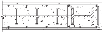
Figure description:
Entity Type: Technical structural cross-section diagram
Key Information:
- Subject: Concrete stiffened steel shear wall with a composite (encased boundary member.
- Central Steel Plate: A continuous horizontal steel shear wall plate.
- Concrete Stiffening: Concrete encasement on both sides of the central steel plate to prevent buckling.
- Shear Connectors: Vertical headed shear studs (I-shaped symbols weld-attached to the plate to ensure composite action with the concrete.
- Composite Boundary Member: A steel I-section (H-shape located at the wall end, fully encased in concrete.
- Reinforcement:
- Longitudinal rebars: Represented by circular dots within the concrete.
- Transverse ties/stirrups: Rectangular steel wraps surrounding the boundary member and longitudinal reinforcement.
Fig. C-H6.2. Concrete stiffened steel shear wall with composite (encased) boundary member.
H6.6 Connections
Two examples of connections between composite walls to either steel or composite boundary elements are shown in Figures C-H6.1 and C-H6.2.
H6.6a Demand Critical Welds
In addition to the welds at the column splices and base plates, the welds at the connections between the boundary elements are potentially subjected to large inelastic excursions and so are designated as demand critical.
H6.6b HBE-to-VBE Connections
The provisions of Section F5 are invoked to provide adequate strength in the boundary element connections.
H6.6c Connections of Steel Plate to Boundary Elements
The Provisions require that the connections between the plate and the boundary members be designed to develop the nominal shear strength of the plate.
H6.6d Connections of Steel Plate to Reinforced Concrete Panel
The thickness of the concrete encasement and the spacing of steel anchors should be calculated to allow the steel plate to reach yield prior to overall or local buckling. It is recommended that overall buckling of the composite panel be checked using elastic buckling theory with a transformed section stiffness for the wall. It is recommended that local steel plate buckling be checked using elastic buckling theory considering steel connectors as fixed plate support points (Choi et al., 2009).