Members that are not part of the seismic force-resisting system (SFRS) and their con- nections may incur forces in addition to gravity loads as a result of story deflection of the SFRS during a seismic event. ASCE/SEI 7, Section 12.12.4, requires structural components that are not considered part of the SFRS to be able to resist the combined effects of gravity loads with any additional forces resulting from the design earth- quake displacement from seismic forces. The load effect due to the design earthquake displacement should be considered as an ultimate or factored load. Inelastic deforma- tions of members and connections at these load levels are acceptable provided that instabilities do not result.
Nonuniform drifts of adjacent story levels may create significant bending moments in multistory columns. These bending moments will usually be greatest at story levels. Inelastic yielding of columns resulting from these bending moments can be accommodated when suitable lateral bracing is provided at story levels and when column shapes have adequate compactness (Newell and Uang, 2008). High shear forces at column splices resulting from these bending moments are addressed by the required shear strength requirements of Section D2.5c. The requirements for column splice location in Section D2.5a are intended to locate splices where bending moments are typically lower. Similarly, shear forces at column bases resulting from story drift are addressed by the requirements in Section D2.6b.
The effect of the design earthquake displacement will also create additional axial forces in beams and girders due to column inclination in both single-story and multistory columns. Connections of columns to beams or diaphragms should be designed to resist horizontal forces that result from the effects of the inclination of the columns. For single-story columns, and multistory columns where the inclination is constant, only the effect of the beam reactions at the story level requires a horizontal thrust to create equilibrium at that story level. However, for multistory columns where the column inclination varies between adjacent levels, the entire column axial force participates in creating a horizontal thrust for equilibrium. Figure C-D3.1 gives a comparison of the effect of column inclination on horizontal force at story level. Likewise, unequal drifts in multistory columns induce both flexure and shear in the column. Flexure will not be induced in columns with constant inclination and simple connections to beams.
Equivalent lateral force analysis methods have not been developed with an eye toward accurately estimating differences in story drift. Use of a modal response spectrum analysis to estimate differences in story drift is also problematic as this quantity is
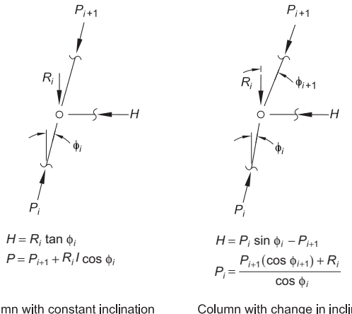
Figure description:
This image contains force analysis diagrams and equations for columns with constant and changing inclinations.
Key Entities & Information
-
Column with constant inclination:
- Forces: (upper axial, (vertical load, (horizontal force, and (lower axial.
- Angle: Constant inclination .
- Equations:
-
Column with change in inclination:
- Forces: Similar setup but with axial forces acting at different angles.
- Angles: Upper inclination and lower inclination .
- Equations:
Column with constant inclination
Column with change in inclination
Fig. C-D3.1. Effect of column inclination on horizontal story force.
not tracked mode by mode in typical software. However, column shear can be tracked modally. Also, the horizontal thrust can be determined by detaching the column from the diaphragm and introducing a link element. Alternatively, thrust can be calculated from the change in column inclination, which can be estimated from the moment and can be tracked mode by mode.
Properly designed simple connections are required at beam-to-column joints to avoid significant flexural forces. As indicated in Specification Section J1, inelastic deformation of the connections is an acceptable means of achieving the required rotation. Standard shear connections addressed in Part 10 of the AISC Steel Construction Manual (AISC, 2017) can be considered to allow adequate rotation at the joints without significant flexural moments. Double angles supporting gravity loads have been shown to attain maximum rotations of 0.05 to 0.09 rad and are suitable for combined gravity and axial forces, as are tee connections that have demonstrated rotations of 0.05 to 0.07 rad (Astaneh-Asl, 2005b). Single-plate connections (single plates), while inherently more rigid than double angles, have been shown to withstand gravity rotations ranging from 0.026 to 0.103 rad and cyclic rotations of 0.09 rad (Astaneh-Asl, 2005a). Note that reducing the number of bolts in the single plate, and consequently the connection depth, increases the maximum possible rotation. Other connections at beam-to-column joints are acceptable if they are configured to provide adequate rotational ductility. Part 10 of the AISC Steel Construction Manual provides guidance on rotational ductility of end-plate and tee connections that can be applied to many types of connections to ensure ductile behavior.
Beams and columns connected with moment connections that may experience inelastic rotation demands as a result of story drift should be detailed to maintain gravity support and provide any required resistance to seismic forces, such as axial collector forces, at the design earthquake displacement. Connections meeting the requirements of ordinary moment frames or conforming to the requirements of gusseted beam-to-column connections for special concentrically braced frames, eccentrically braced frames, and buckling-restrained braced frames provide such resistance and deformation capacity.