H5.1 Scope
The provisions in this section apply to reinforced concrete shear walls with composite boundary elements and coupled reinforced concrete shear walls, with or without composite boundary elements, with structural steel or composite coupling beams that connect two or more adjacent walls. Examples of boundary element conditions are discussed in Commentary Section H4.1. The following focuses on coupled composite special shear walls (C-SSW).
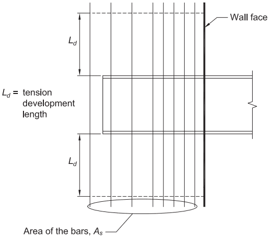
Figure description:
Key Entities & Information:
- Wall face: Represented by the thick vertical line on the right, indicating the boundary of the concrete shear wall.
- Embedded Beam: A horizontal structural steel or composite coupling beam extending into the wall.
- Vertical Reinforcement: Multiple vertical lines representing wall longitudinal bars with a collective area designated as .
- (Tension Development Length: Specified as the minimum length for the vertical reinforcement bars to extend both above and below the embedded beam profile to ensure proper tension development.
- Configuration: Illustrates wall longitudinal reinforcement crossing the embedment length of a coupling beam within a composite special shear wall (C-SSW.
Fig. C-H4.5. Wall longitudinal reinforcement crossing embedment length.
For cases in which special reinforcement detailing in the wall boundary region is required, it is not necessary, nor is it typically practical, to pass wall boundary transverse reinforcing bars through the web of the embedded coupling beam. A practical alternative is to provide transverse reinforcement confining the region around the embedded coupling beam in the form of hoops and cross ties as shown in Figure C-H5.1.
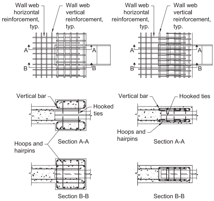
Figure description:
The image contains engineering diagrams illustrating the reinforcement detailing for an embedded coupling beam in a wall boundary region.
Key Components & Entities:
- Wall Reinforcement: Consists of typical wall web horizontal and vertical reinforcement bars.
- Boundary Region Reinforcement: Features transverse reinforcement in the form of hoops, cross ties, and hairpins.
- Vertical Bars: Includes wall longitudinal bars and additional bars used to tie hoops and hairpins.
- Sections A-A & B-B:
- Section A-A: Shows the top view of the region around the embedded beam, highlighting the use of vertical bars, hooked ties, hoops, and hairpins to confine the area without passing bars through the beam web.
- Section B-B: Shows the bottom view of the confinement detailing below the beam.
- Configuration Variants: The diagram shows two different arrangements (left and right for the boundary region confinement reinforcement.
Note: Vertical bars are wall longitudinal bars and additional bars to tie hoops, hairpins, or hooked ties.
(a) Steel coupling framing into "barbell" wall boundary region
- (b) Steel coupling beam framing into rectangular wall boundary region
Fig. C-H5.1. Example details of a steel coupling beam embedded in a reinforced concrete wall.
H5.2 Basis of Design
The preferred sequence of yielding for coupled walls is for the coupling beams to yield over the entire height of the structure prior to yielding of the walls at their bases (Santhakumar, 1974). This behavior relies on coupling beam-to-wall connections that can develop the expected flexural and shear strengths of the coupling beams. For steel coupling beams, or steel beams embedded within composite coupling beams, satisfying the requirements of Section F3.5b provides adequate ductility for shear yielding. For a composite coupling beam, the shear strengths in Equations H5-1 and H5-1M are assessed assuming the minimum shear reinforcement requirements from ACI 318 are satisfied, thus enabling the coupling beam to yield in shear.
H5.3 Analysis
Wall piers in special shear walls will experience significant cyclic plastic deformations. Appropriate stiffness values need to be selected to account for the differences between the cracked section properties of the walls in the plastic hinge region and regions that are expected to remain elastic. Guidance from ACI 318 Chapter 6 (Sections 6.6.3.1.1, 6.6.3.1.2, 6.6.4.2, 6.7.1.3) and ASCE 41 is available, as well as Commentary Chapter C. Additional guidance may be found in PEER/TBI (2017) and LATBSDC (2017).
To account for spalling at the coupling beam-to-wall connection, the value of (discussed in Commentary Section H4.3) needs to be computed based on clear span + 2(clear cover) to the first layer of confining reinforcement in the wall boundary member.
H5.4 System Requirements
In coupled walls, the coupling beam forces can be redistributed vertically over the wall height to lower the required wall axial strength and improve constructability by permitting engineers to use one beam section over larger vertical portions of the wall. Given the benefits of redistribution and the inherent ductility of steel coupling beams, a 20% redistribution of coupling beam design forces is permitted, provided the sum of the resulting shear strength (e.g., the design strength, ) exceeds the sum of the coupling beam design force determined from the lateral loading (e.g., the required strength using LRFD load combinations, ) (CSA, 2004); that is, . This concept is schematically illustrated in Figure C-H5.2.
To help ensure ductile response of the coupled walls, (a) the required axial strength of the walls is determined based on the assumption that all of the coupling beams are yielding over the height of the wall, and (b) the required axial strength is less than the balance point in the wall; in other words, the nominal strength of the wall is governed by tensile yielding. The calculated earthquake axial force is multiplied by the following overstrength factor:
(C-H5-1)
where is the expected strain-hardened strength of the coupling beams and is the required strength of the coupling beams calculated by analysis.
The required wall overstrength can have a significant effect on wall pier design forces (Fortney, 2005; Harries and McNeice, 2006) and will typically be greater in structures having a higher coupling ratio due to the relatively steep gradient of beam shear demand over the height of the structure as illustrated in Figure C-H5.2. While the greater coupling ratio tends to reduce the required wall bending moments, the required axial forces are increased. The permitted inelastic redistribution of beam shear forces, as shown in Figure C-H5.2, is intended to mitigate the inherent conservatism in the capacity design requirement for the required axial wall strength.
H5.5 Members
H5.5a Ductile Elements
Coupling beams must be able to undergo substantial inelastic deformation reversals; therefore, coupling beams are designated as protected zones. Well-established guidelines for shear links in eccentrically braced frames need to be followed.
H5.5b Boundary Members
Concerns have been raised that walls with encased steel boundary members may have a tendency to split along planes 1 and 2 shown in Figure C-H5.3. Transverse reinforcement within a distance , where is the width of the wall, will resist splitting along plane 1 while the wall horizontal reinforcement will be adequate to prevent failure along plane 2. The detailing of web cross-ties is governed by the requirements ACI 318, Chapter 18.
H5.5c Steel Coupling Beams
A coupling beam rotation equal to 0.08 rad reflects the upper limit of link rotation angle in EBF. It should be noted that 0.08 rad may be conservative for coupled walls, in which case using this rotation will result in extra stiffeners in the coupling beam.
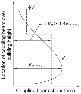
Figure description:
Location of coupling beam over building height vs. Coupling beam shear force
Distribution of Coupling Beam Shear Force and Strength over Building Height
Legend
- — color: black; symbol: Solid line
- — color: black; symbol: Dashed line
Annotations
- (text_label - position: at the peak of the curve (height ≈ 0.25))
- (text_label - position: distance from y-axis to dashed line at mid-height (height ≈ 0.5))
| Relative Height | (Shear demand) | (Shear strength) |
|---|---|---|
| 0.05 | 4.0 | 6.5 |
| 0.10 | 5.5 | 6.5 |
| 0.15 | 7.0 | 6.5 |
| 0.20 | 8.0 | 6.5 |
| 0.25 | 8.2 | 6.5 |
| 0.30 | 8.0 | 6.5 |
| 0.40 | 7.2 | 6.5 |
| 0.50 | 6.0 | 6.5 |
| 0.60 | 4.8 | 6.5 / 2.0 |
| 0.70 | 3.8 | 2.0 |
| 0.80 | 2.8 | 2.0 |
| 0.90 | 1.5 | 2.0 |
| 0.95 | 1.0 | 2.0 |
Notes: The data values are estimated relative coordinates as the original chart does not provide a numerical scale. represents the ultimate shear force demand curve, and represents the design shear strength, which is shown as a stepped capacity envelope.
Fig. C-H5.2. Vertical distribution of coupling beam shear.
A smaller value of link rotation may be used if established by rational analysis to determine the inelastic deformation demands expected at the design earthquake displacement.
In addition to the potential use of stiffeners along the span between the reinforced concrete walls, face bearing plates must be provided at the face of the wall. Face bearing plates are full-width stiffeners located on both sides of the web that, in effect, close the opening in the concrete form required to install the beam. Face bearing plates provide confinement and assist in transfer of loads to the concrete through direct bearing. If it is convenient for formwork, face bearing plates may extend beyond the flanges of the coupling beam, although the plate must be installed on the inside of the form and is thereby flush with the face of the wall. The face bearing plates are detailed as a stiffener at the end of a link beam as required in Section F3.5b.4. Near the end of the embedded region, additional stiffeners similar to the face bearing plates need to be provided. In cases where vertical transfer bars are used, these stiffeners are to be aligned with the vertical transfer bars near the end of the embedded region.
In addition to boundary element reinforcing, two regions of vertical “transfer bars” may be provided to assist in the transfer of vertical forces and thus improve the embedment capacity (Shahrooz et al., 1993; Gong and Shahrooz, 2001a, 2001b; Fortney, 2005). Evaluation of experimental data in which transfer bars had been used (Gong and Shahrooz, 2001a, 2001b; Fortney, 2005) indicates that the minimum required area of vertical transfer reinforcement is as follows (see Figure C-H5.4):
(C-H5-2)
where
The transfer bars need to be placed close to the face of the wall and near the end of embedment length in order to develop an internal force couple that can alleviate the bearing stresses around the flanges and improve the energy dissipation characteristics of coupling beam-to-wall connections (Gong and Shahrooz, 2001a, 2001b).
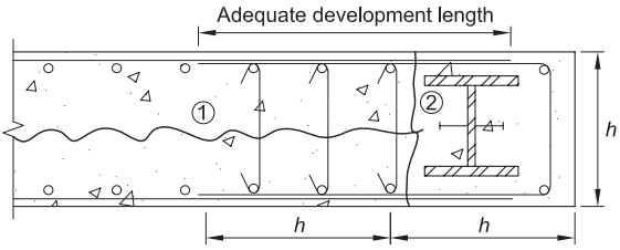
Figure description:
Key Information:
- Subject: Reinforcement detail for a coupling beam-to-wall connection to prevent splitting failures.
- Key Entities:
- Steel Section: An I-shaped structural steel member embedded in concrete.
- Reinforcement Bars: Longitudinal and transverse bars surrounding the steel section.
- Transfer Bars (indicated by 1 and 2: Placed near the face of the wall and the end of the embedment.
- Dimensions & Specifications:
- h: Total depth of the concrete section.
- Development Length: Labeled as "Adequate development length" extending across the reinforcement zone.
- Spacing: Two distinct regions of length h are shown for placement of reinforcement around the embedded steel.
Fig. C-H5.3. Reinforcement to prevent splitting failures.
Although the required embedment length of the coupling beam may be reduced if the contribution of these bars is taken into account (Qin, 1993), to avoid excessive inelastic damage in the connection region, it is recommended by Harries et al. (1997) and Shahrooz et al. (1993) that the contribution of the transfer bars be neglected in the determination of the required embedment length. The vertical transfer bars may be attached directly to the top and bottom flanges or be passed through holes in the flanges and mechanically anchored by bolting or welding. The use of mechanical half couplers that are welded to the flanges has been successfully tested (Gong and Shahrooz, 2001a, 2001b; Fortney, 2005). U-bar hairpin reinforcement anchored by the embedded coupling beam may also be used, as shown in Figure C-H5.5. These hairpins will be alternated to engage the top and bottom flanges. The transfer bars have to be fully developed in tension either by providing an adequate tension development length or through the use of headed bars. In order to prevent congestion, the sum of the areas of transfer bars and wall longitudinal bars over the embedment length ( shown in Figure C-H5.4 or the area of U-bar hairpins in Figure C-H5.5) is limited to of the wall cross section taken as the wall width times the embedment length.
The vertical transfer bars shown in Figure C-H5.4 are a suggested detail for beams located at a floor level where the wall piers extend far enough above the floor/roof level to accommodate the vertical transfer bars. For coupling beams located at the roof level where the wall piers do not extend far enough above the floor/roof level, alternate details will need to be considered. Such alternate details are presented and discussed in El-Tawil et al. (2009).
Equations H5-1 and H5-1M are derived using the same method as described for Equations H4-4 and H4-4M (see Commentary Section H4.5b).
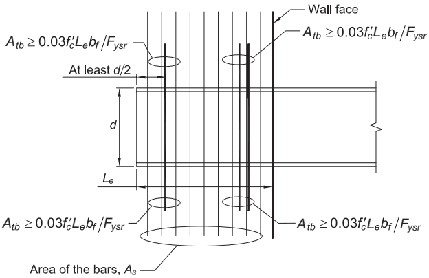
Figure description:
Structural Diagram: Transfer Bars (Fig. C-H5.4
-
Key Entities:
- Embedded Steel Beam: Defined by depth and embedment length .
- Wall Face: Vertical boundary of the concrete structure.
- Transfer Bars (: Transverse reinforcement bars required at specific locations.
- Vertical Bars (: Longitudinal reinforcement through the connection area.
-
Governing Formula for Transfer Bar Area (:
- Where is concrete strength, is embedment length, is flange width, and is reinforcement yield strength.
-
Spatial Constraints:
- The first set of transfer bars must be placed at a distance of at least from the embedded end of the beam.
- Reinforcement is distributed within the embedment zone relative to the wall face.
Fig. C-H5.4. Transfer bars.
H5.5d Composite Coupling Beams
The required embedment length needs to be calculated to ensure that the capacity of the composite coupling beam is developed. Based on analytical studies, which were verified against experimental data, Gong and Shahrooz (2001a) proposed an equation in which a single material overstrength factor had been specified for computing the contribution of concrete and transverse reinforcement towards the shear strength of composite coupling beams. In that equation, the specified concrete compressive strength, , and specified minimum yield stress of transverse reinforcement, , were to be used. Equations H5-5 and H5-5M are revised versions of the original equation in order to more transparently differentiate between the material overstrength factors for concrete and reinforcing steel. The coefficients in this equation were calibrated in order to obtain the same values as those from the original form of the equation published by Gong and Shahrooz (2001a, 2001b).
H5.5e Protected Zones
Coupling beams are expected to undergo significant inelastic deformations. With the exception of face bearing plate and web stiffener attachments, the entire clear span is designated as a protected zone.
H5.6 Connections
Structural steel sections as boundary elements in C-SSW are anticipated to undergo significant inelastic deformations, particularly in the plastic hinge region. The boundary columns have to be adequately anchored to the foundation system. Equally important are the splices along the boundary columns. These connections are designated as demand critical welds.
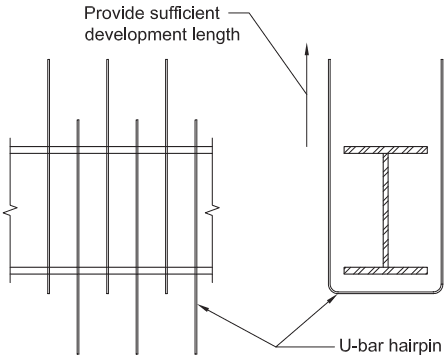
Figure description:
- Subject: Structural detail of alternating U-shaped hairpin reinforcement for boundary elements in Composite Special Shear Walls (C-SSW.
- Key Entities:
- Structural Steel Section: An I-beam acting as a boundary column.
- U-bar Hairpins: Reinforcing bars that wrap around the steel section.
- Alternating Pattern: Hairpins are installed in alternating orientations (upward and downward.
- Critical Requirements:
- Development Length: Arrows indicate that vertical legs must have sufficient length for proper anchorage.
- Function: Necessary for anchoring boundary columns to foundations and managing inelastic deformations in plastic hinge regions.
Fig. C-H5.5. Alternating U-shaped hairpins.