A3.1 Material Specifications
The structural steels that are explicitly permitted for use in seismic applications have been selected based upon their inelastic properties and weldability. In general, they meet the following characteristics: (a) a pronounced stress-strain plateau at the yield stress; (b) a large inelastic strain capability—for example, a tensile elongation of 20% or greater in a 2 in. (50 mm) gage length; and (c) good weldability. Other steels should not be used without evidence that these criteria are met.
The limitation on the specified minimum yield stress for members expecting inelastic action refers to inelastic action under the effects of the design earthquake. The 50 ksi (345 MPa) limitation on the specified minimum yield stress for members was restricted to those systems in Chapters E, F, G, and H expected to undergo moderate to significant inelastic action, while a 55 ksi (380 MPa) limitation was assigned to the systems in Sections E1, F1, G1, H1, and H4 because those systems are expected to undergo limited inelastic action. The listed steels conforming to ASTM A1011/ A1011M with a specified minimum yield stress of 55 ksi (380 MPa) are included as they have adequate ductility considering their limited thickness range. The steel is commonly used by the metal building industry in built-up sections.
An exception to the limitations that the specified minimum yield stress not exceed 50 ksi (345 MPa) allows the yield stress limit to be exceeded where the material is determined to be suitable through testing or other rational criteria. An example of testing that would permit higher strength steels for elements would be cyclic tests conducted according to Sections K2 and K3 where the element is subject to the anticipated level of inelastic strain for the intended use. An example of rational criteria to allow for exceedance of the specified minimum yield stresses would include very conservative design assumptions for the given ordinary system. These assumptions would include designing the ordinary system with the ASCE/SEI 7 (ASCE, 2022) design earthquake and an equal to 1.0 , so that the required strength in all structural components (members and connections) is less than 0.67 of the available strength; in other words, the demand-to-capacity ratio is less than . Because the maximum considered earthquake (MCE) is 1.5 times that of the design earthquake, these assumptions are equivalent to stating that the ordinary system needs to be designed to remain essentially elastic at the MCE with .
Modern steels of higher strength, such as ASTM A913/A913M Grades 65 (450) and 70 (485), are generally considered to have properties acceptable for seismic column applications where limited inelastic action may occur. An exception permits structural steel with a specified minimum yield stress up to 70 ksi (485 MPa) for columns in moderate to highly ductile systems where the anticipated level of inelastic yielding will be minor.
Conformance with the material requirements of the Specification is satisfied by the testing performed by the manufacturer in accordance with the corresponding ASTM provisions. Supplemental or independent material testing is only required for material that cannot be identified or traced to a material test report and materials used in qualification testing, according to Section K2.
While ASTM A709/A709M steel is primarily used in the design and construction of bridges, it could also be used in building construction and thus, has been added to the Provisions. Written as an umbrella specification, its grades are essentially the equivalent of other approved ASTM specifications. For example, ASTM A709/A709M Grade 50 (345) is essentially ASTM A572/A572M Grade 50 (345) and ASTM A709/A709M Grade 50W (345W) is essentially ASTM A588/A588M Grade 50 (345).
ASTM A1085/A1085M hollow structural sections (HSS) have tighter mass tolerances, a maximum specified yield stress, specified minimum Charpy V-notch (CVN) requirements, and a reduced variability of material yield stress and tensile stress versus the ASTM A500/A500M Grades B and C HSS and ASTM A53/A53M Grade B pipe materials. There is ongoing research to determine if A1085/1085M material offers any advantages when used in certain SFRS applications.
For rotary-straightened W-shapes, an area of reduced notch toughness has been documented in a limited region of the web immediately adjacent to the flange/web fillet as illustrated in Figure C-A3.1. Recommendations issued by AISC (AISC, 1997a) were followed up by a series of industry sponsored research projects (Kaufmann et al., 2001; Uang and Chi, 2001; Kaufmann and Fisher, 2001; Lee et al., 2002;
Bartlett et al., 2001). This research generally corroborates AISC’s initial findings and recommendations.
A3.2 Expected Material Strength
The Provisions employ a methodology for many seismic systems (e.g., special moment frames, special concentrically braced frames, and eccentrically braced frames) that can be characterized as “capacity design.” That is, the required strength of elements that are intended to behave essentially elastically is defined by forces corresponding to the capacity (expected strength) of certain members or components intended to undergo inelastic deformations (e.g., the link in eccentrically braced frames). This methodology serves to confine ductility demands to members or components that have specific requirements to force their ductile behavior. Furthermore, within that member or component, the desired ductile mode of yielding will govern and other nonductile modes will be precluded.
Such a capacity-design methodology requires a realistic estimate of the expected strength of the members or components intended to undergo inelastic deformations (designated yielding members). To this end, the average yield stresses of various steel materials have been established by a survey of mill certificates, and the ratio of average yield stress to nominal yield stress has been included in the Provisions as . The expected capacity of the designated yielding member is defined as times the nominal strength of the member based on the desired yield mode. This expected strength is amplified to account for strain hardening in some cases. For determination of the required strength of adjoining elements and their connection to the designated yielding members, neither the resistance factor (LRFD) nor the safety factor (ASD) are applied to the strength of the designated yielding members.
Where the capacity-design methodology is employed to preclude nonductile or unintended modes of failure within the designated yielding member, it is reasonable to use the expected material strength in the determination of the element capacity. For unintended modes of failure, the factor applies to the determination of available
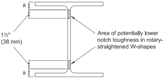
Figure description:
Key Information:
- Subject: Diagram of the "k-area" in a structural steel W-shape (I-beam.
- Critical Region: The hatched zones on the web, located adjacent to the fillet, are identified as areas of potentially lower notch toughness in rotary-straightened W-shapes.
- Dimensions:
- k: The distance from the outer face of the flange to the toe of the fillet.
- Affected Zone: Extends 1½" (38 mm from the dimension into the web.
Fig. C-A3.1. "k-area."
strength just as it applies to the determination of the designated yielding member capacity used to compute the required strength and to the strength with respect to the limit states to be precluded. An example of this condition is the design of the beam outside the link in an eccentrically braced frame for the yield limit states. The required strength is based on the capacity of the link beam. The yield limit states of the beam outside the link, such as combined flexure and compression, can be expected to be similarly affected by increased material strength, thus the factor is applied when determining the available strength. The factor is not applied to elements other than the designated yielding element.
Similarly, rupture limit states within the designated yielding element are affected by increased material strength. Examples of such limit states include block shear rupture and net section rupture of braces in special concentrically braced frames, where the required strength is calculated based on the brace capacity in tension. The ratio of expected tensile strength to specified minimum tensile strength is often different from that of expected yield stress to specified minimum yield stress, so a separate factor was created called . This factor applies only to rupture limit states in designated yielding members. As is the case with is applied in the determination of the expected strength of designated yielding members and not the available strength of other members.
The specified values of for rolled shapes are somewhat lower than those that can be calculated using the mean values reported in a survey conducted by the Structural Shape Producers Council (SSPC, 1994). Those values were skewed somewhat by the inclusion of a large number of smaller members, which typically have a higher measured yield stress than the larger members common in seismic design. The given values are considered to be reasonable averages, although it is recognized that they are not maxima. The expected yield stress, , can be determined by testing conducted in accordance with the requirements for the specified grade of steel. Such an approach should only be followed in unusual cases where there is extensive evidence that the values of in Table A3.2 are significantly unconservative. It is not expected that this would be the approach followed for typical building projects. Refer to ASTM A370 for testing requirements. The higher values of for ASTM A36/A36M ) shapes are indicative of the most recently reported properties of these grades of steel. The values of will be periodically monitored to ensure that current production practice is properly reflected.
Two studies (Liu et al., 2007; Liu, 2016) were used in determining the values shown in Table A3.2. These values are based on the mean value of for individual samples. Mean values are considered to be sufficiently conservative for these calculations considering that they are applied along with a factor of 0.75 . An additional analysis of tensile data was carried out (Harrold, 2004) to determine appropriate and factors for ASTM A529/A529M Grade 50 (345), A529/A529M Grade 55 (380), A1011/A1011M HSLAS Grade 55 (380), and A572/A572M Grade 55 (380) steels.
ASTM A501/A501M material has shown through limited testing to have values less than those specified in Table A3.2 as this material is not cold worked as is ASTM A500/A500M material. Presently, ASTM A501/A501M material is not as commonly used nor as readily available as ASTM A500/A500M (Grades B or C). Due to the limited production data available for ASTM A501/A501M, these Provisions continue to conservatively use and values for ASTM A501/A501M based primarily on ASTM A500/A500M (Grades B or C) production data.
For ASTM A709/A709M material, the listed materials of Grades 36 (250), 50 (345), 50S (345S), 50W (345W), QST 50 (QST 345), QST 50S (QST 345S), QST 65 (QST 450), and QST 70 (QST 485) are also included in ASTM Specifications A36/A36M, A572/A572M, A992/A992M, A588/A588M, and A913/A913M, respectively. When the supplementary requirements of ASTM A709/A709M are specified, they exceed the requirements of ASTM A36/A36M, A572/A572M, A992/A992M, A588/A588M, and A913/A913M. Table A3.2 has been updated accordingly to reflect these and values
ASTM A572/A572M Grade 42 (290) shapes are not commonly produced. However, thick plate sections of this material grade are still used for connections, built-up shapes, and column bases. As limited production data is available for plates of this material grade, a value of of 1.3 is specified corresponding to approximately the same 55 ksi (380 MPa) expected yield stress as ASTM A572/A572M Grade 50 (345) plate. The value of 1.0 specified for plates of this material grade considers the expected tensile strength, , of the material to be the same as the specified tensile strength, , which is conservative when used for determining nominal strength.
Values of and for ASTM A1043/A1043M Grades 36 (250) and 50 (345) are included based on an AISC survey of production data.
Unpublished data from American reinforcing bar producers indicate , and for A615/A615M Grade 60 (420), and , and for A615/A615M Grade 75 (520). Similarly, , and for A706/A706M Grade 60 (420) are expected. Thus, the values in Table A3.2 are conservative. These values are meant for new construction and Americanproduced bars, and do not apply to other grades or specifications.
The specified value of is based on the value specified in ACI 318 (ACI, 2019).
A3.3 Heavy Sections
The Specification requirements for notch toughness cover hot-rolled shapes with a flange thickness exceeding 2 in. (50 mm) and built-up heavy shapes with plate elements with thickness exceeding 2 in. (50 mm) in tension applications. In the Provisions, this requirement is extended to cover the following: (a) shapes that are part of the SFRS with flange thickness greater than or equal to in. (38 mm); and (b) plate elements with thickness greater than or equal to 2 in. (50 mm) that are part of the SFRS, such as the flanges of built-up girders and connection material subject to inelastic strain under seismic loading. Because smaller shapes and thinner plates are generally subjected to sufficient cross-sectional reduction during the rolling process such that the resulting notch toughness will exceed that required (Cattan, 1995), specific requirements are not included herein.
Connection plates in which inelastic strain under seismic loading may be expected include, but are not limited to the following:
- (1) Gusset plates for diagonal braces that are designed to allow rotation capacity as specified in Section F2.6c.3(b)
- (2) Bolted flange plates for moment connections, such as specified in the AISC Prequalified Connections for Special and Intermediate Steel Moment Frames for Seismic Applications (ANSI/AISC 358) (AISC, 2022b) Chapter 7, hereafter referred to as ANSI/AISC 358, and similar flangeplate moment connections in ordinary moment frame systems
- (3) Bolted end-plates for moment connections, such as specified in ANSI/AISC 358, Chapter 6
- (4) Base plates of column bases designed to yield inelastically to limit forces on anchor rods or to allow column rotation
The requirements of this section apply to all members of the seismic force-resisting system (SFRS). For example, a designer might include a member in the SFRS to develop a more robust load path, but the member will experience only an insignificant level of seismic demand. An example of such a member might include a transfer girder with thick plates where its design is dominated by its gravity load demand. It would be inconsistent with the intent of this section if the designer were to arbitrarily exclude a member with insignificant seismic loads from the SFRS that would otherwise improve the seismic performance of the building in order to avoid the toughness requirements in this section. The requirements noted in this discussion would still apply in this case.
Early investigations of connection fractures in the 1994 Northridge earthquake identified a number of fractures that some speculated were the result of inadequate through-thickness strength of the column flange material. As a result, in the period immediately following the Northridge earthquake, a number of recommendations were promulgated that suggested limiting the value of through-thickness stress demand on column flanges to ensure that through-thickness yielding did not initiate in the column flanges. This limit state often controlled the overall design of these connections. However, the actual cause for the fractures that were initially thought to be through-thickness failures of the column flange are now considered to be unrelated to this material property. Detailed fracture mechanics investigations conducted as part of the FEMA/SAC project confirm that damage initially identified as through-thickness failures is likely to have occurred as a result of certain combinations of filler metal and base material strength and notch toughness, conditions of stress in the connection, and the presence of critical flaws in the welded joint. In addition to the analytical studies, extensive through-thickness testing conducted specifically to determine the susceptibility to through-thickness failures of column materials meeting ASTM A572/A572M Grade 50 (345) and ASTM A913/A913M Grade 65 (450) did not result in significant through-thickness fractures (FEMA, 2000f).
In addition, none of the more than 100 full-scale tests on “post-Northridge” connection details have demonstrated any through-thickness column fractures. This combined analytical and laboratory research clearly shows that due to the high restraint inherent in welded beam flange-to-column flange joints, the through-thickness yield and tensile strengths of the column material are significantly elevated in the region of the connection. For the materials tested, these strengths significantly exceed those loads that can be delivered to the column by the beam flange. For this reason, no limits are suggested for the through-thickness strength of the base material by the FEMA/SAC program or in these Provisions.
The preceding discussion assumes that no significant laminations, inclusions, or other discontinuities occur in regions adjacent to welded beam flange-to-column flange joints and other tee and corner joints. Section J7.2c checks the integrity of this material after welding. A more conservative approach would be to ultrasonically test the material for laminations prior to welding. A similar requirement has been included in the Los Angeles City building code since 1973; however, in practice the base material prior to welding generally passes the ultrasonic examination, and interior defects, if any, are found only after heating and cooling during the weld process. Should a concern exist, the ultrasonic inspection prior to welding should be conducted in accordance with ASTM A435/A435M (ASTM, 2017b) for plates and ASTM A898/ A898M (ASTM 2017a), level 1, for shapes.
A3.4 Consumables for Welding
As in previous Provisions, specified levels of filler metal and weld metal CVN toughness are required in all member and connection welds in the load path of the SFRS.
The Provisions designate certain welds as demand critical welds and require that these welds be made with filler metals that meet minimum levels of CVN toughness using two different test temperatures and specified test protocols, unless otherwise exempted from testing. Welds designated as demand critical welds are identified in the section of the Provisions applicable to the specific SFRS. Demand critical welds are generally complete-joint-penetration (CJP) groove welds, so designated because they are subjected to yield level or higher stress demand and located in a joint where failure would result in significant degradation in the strength or stiffness of the SFRS.
For demand critical welds, FEMA 350 (FEMA, 2000a) and FEMA 353 (FEMA, 2000b) recommended filler metal that complied with minimum CVN requirements using two test temperatures and specified test protocols. Earlier editions of the Provisions included the dual CVN requirement suggested in the FEMA documents but required a lower temperature than the FEMA recommendations for the filler metal classification, rather than . The use of this lower temperature was consistent with the filler metal used in the SAC/FEMA tests and matched the filler metals frequently used for such welds at the time the testing was conducted. The filler metal classification requirement was revised in the 2010 edition of the
Provisions (AISC, 2010b) to reflect the original FEMA recommendation and AWS Structural Welding Code—Seismic Supplement (AWS D1.8/D1.8M) (AWS, 2009) requirements because filler metals classified at either temperature ensure that some ductile tearing would occur before final fracture and because the more critical CVN weld metal property is the minimum of 40 ft-lbf (54 J) at 70°F (21°C), as determined in AWS D1.8/D1.8M, Annex A. This change permitted the use of common welding processes and filler metals, such as gas metal arc welding and submerged are welding filler metals that are frequently classified for 20 ft-lbf (27 J) at 0°F (–18°C).
In a structure with exposed structural steel, an unheated building, or a building used for cold storage, the demand critical welds may be subjected to service temperatures less than 50°F (10°C) on a regular basis. In these cases, the Provisions require that the minimum qualification temperature for AWS D1.8/D1.8M, Annex A, be adjusted such that the test temperature for the CVN toughness qualification tests be no more than 20°F (11°C) above the lowest anticipated service temperature (LAST) for 70 ksi (480 MPa) and 80 ksi (550 MPa) filler metals and no more than LAST for 90 ksi (620 MPa) filler metals. For example, weld metal in a structure with a LAST of 0°F (–18°C) would need to be qualified at a test temperature less than or equal to 20°F (–7°C) in lieu of 70°F (21°C) for 70 ksi (480 MPa) and 80 ksi (550 MPa) filler metals and less than or equal to 0°F (–18°C) in lieu of 50°F (10°C) for 90 ksi (620 MPa) filler metals. For purposes of the Provisions, the LAST may be considered to be the lowest one-day mean temperature compiled from National Oceanic and Atmospheric Administration data.
All other welds in members and connections in the load path of the SFRS require filler metal with a specified minimum CVN toughness of 20 ft-lbf (27 J) at 0°F (–18°C) for 70 ksi (480 MPa) and 80 ksi (550 MPa) filler metals and 25 ft-lbf (34 J) at –20°F (–30°C) for 90 ksi (620 MPa) filler metals using the AWS A5 classification. Manufacturer certification may also be used to meet this CVN requirement. Welds carrying only gravity loads, such as filler beam connections and welds for collateral members of the SFRS, such as deck welds, minor collectors, and lateral bracing, do not require filler metal meeting these notch toughness requirements.
It is not the intent of the Provisions to require project-specific CVN testing of either the welding procedure specification or any production welds. Further, these weld notch toughness requirements are not intended to apply to electric resistance welding and submerged arc welding when these welding processes are used in the production of hollow structural sections and pipe, such as ASTM A500/A500M and A53/A53M.
A3.5 Concrete and Steel Reinforcement
The limitations on structural steel grades used in composite construction are the same as those given in Section A3.1. The limitations in Section A3.5 on concrete and reinforcement are the same as those specified for the seismic design of reinforced concrete structures in ACI 318, Chapter 18 (ACI, 2019). While these limitations are particularly appropriate for construction in seismic design categories D, E, and F, they apply in any seismic design category when systems are designed with the assumption that inelastic deformation will be required.