E4.1 Scope
Truss-girder moment frames have often been designed with little or no regard for truss ductility. Research has shown that such truss moment frames have very poor hysteretic behavior with large, sudden reductions in strength and stiffness due to
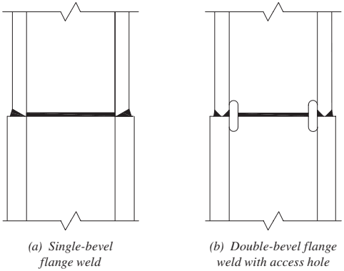
Figure description:
Key Information:
- Subject: Structural splice details for steel members using partial-joint-penetration (PJP groove welds.
- Diagram (a: Single-bevel flange weld, showing a welded connection between two vertical members (flanges without an access hole.
- Diagram (b: Double-bevel flange weld featuring a weld access hole to facilitate the welding process and transition between members.
- Context: These details relate to truss-girder moment frame design considerations for ductility and hysteretic behavior.
Key Entities:
- Splice details
- Partial-joint-penetration (PJP groove welds
- Single-bevel flange weld
- Double-bevel flange weld
- Weld access hole
Fig. C-E3.11. Splice details with partial-joint-penetration (PJP) groove welds.
buckling and fracture of web members prior to or early in the dissipation of energy through inelastic deformations (Itani and Goel, 1991; Goel and Itani, 1994a). The resulting hysteretic degradation as illustrated in Figure C-E4.1 results in excessively large story drifts in building frames subjected to earthquake ground motions with peak accelerations on the order of 0.4g to 0.5g.
Research led to the development of special truss girders that limit inelastic deformations to a special segment of the truss (Itani and Goel, 1991; Goel and Itani, 1994b; Basha and Goel, 1994). As illustrated in Figure C-E4.2, the chords and web members (arranged in an X-pattern) of the special segment are designed to withstand large inelastic deformations, while the rest of the structure remains elastic. Special truss moment frames (STMF) have been validated by extensive testing of full-scale subassemblages with story-high columns and full-span special truss girders. As illustrated in Figure C-E4.3, STMF are ductile with stable hysteretic behavior. The stable hysteretic behavior continues for a large number of cycles, up to story drift.
E4.2 Basis of Design
The span length and depth of the truss girders given in the Provisions are limited to the range used in the test program.
E4.3 Analysis
E4.3a Special Segment
The design procedure of STMF is built upon the concept that the special segment of truss girders will yield in shear under the prescribed earthquake load combinations, while all other frame members and connections remain essentially elastic. Thus, for the purpose of determining the required shear strength of special segments, the truss
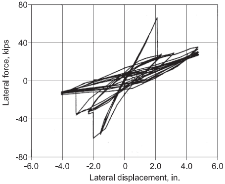
Figure description:
Hysteresis Plot of Lateral Force vs. Lateral Displacement
Lateral force vs Lateral displacement
| Lateral displacement, in. | Lateral force, kips |
|---|---|
| 0.0 | 0.0 |
| 1.0 | 8.0 |
| 1.5 | 15.0 |
| 0.5 | 5.0 |
| -1.0 | -8.0 |
| -1.5 | -15.0 |
| -0.5 | -5.0 |
| 1.5 | 20.0 |
| 2.1 | 67.0 |
| 2.3 | 25.0 |
| 3.5 | 30.0 |
| 4.8 | 36.0 |
| 3.0 | 20.0 |
| 1.0 | 5.0 |
| -1.5 | -20.0 |
| -2.0 | -60.0 |
| -1.8 | -35.0 |
| -3.2 | -38.0 |
| -4.1 | -15.0 |
| -2.5 | -8.0 |
| 0.0 | 2.0 |
| 2.5 | 28.0 |
| 4.5 | 35.0 |
| 3.0 | 15.0 |
| 1.0 | 0.0 |
| -2.0 | -20.0 |
| -3.0 | -35.0 |
| -4.0 | -12.0 |
Notes: The chart illustrates a hysteretic response under cyclic loading. The data path includes multiple overlapping loops with significant force excursions (spikes at approximately 2.1 inches (positive force and -2.0 inches (negative force lateral displacement.)))
Fig. C-E4.1. Strength degradation in undetailed truss girder.
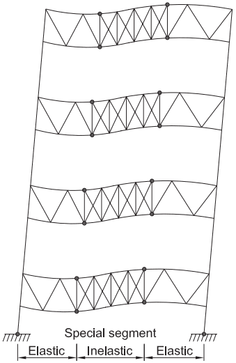
Figure description:
- Subject: Intended yield mechanism of a four-story Special Truss Moment Frame (STMF under lateral displacement.
- Structural Components:
- Vertical Columns: Supporting four levels of trusses.
- Elastic Segments: Outer portions of the trusses (V-bracing designed to remain in the elastic range.
- Inelastic Special Segment: Central portion of the trusses (diagonal/X-bracing where yield is localized.
- Key Mechanism:
- Plastic Hinges: Form at the four corners of each special segment (indicated by circular dots.
- Deformation: Lateral sway causes significant shear deformation and inelastic activity concentrated in the central special segment while the rest of the frame remains elastic.
Fig. C-E4.2. Intended yield mechanism of STMF with diagonal web members in special segment.
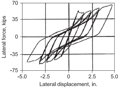
Figure description:
Lateral Hysteresis Response Lateral Force vs. Lateral Displacement
Hysteretic Behavior of Component
| Lateral displacement (in.) | Lateral force (kips) |
|---|---|
| 0.0 | 0 |
| 0.8 | 15 |
| 1.5 | 45 |
| 1.1 | 15 |
| 0.6 | 0 |
| 0.0 | -15 |
| -0.5 | -30 |
| -0.8 | -15 |
| -0.3 | 10 |
| 0.1 | 25 |
| 1.5 | 45 |
| 2.2 | 55 |
| 1.5 | 20 |
| 0.8 | 0 |
| 0.0 | -20 |
| -1.0 | -35 |
| -2.2 | -55 |
| -1.5 | -15 |
| -0.8 | 15 |
| 0.0 | 30 |
| 1.5 | 45 |
| 3.2 | 62 |
| 2.2 | 25 |
| 1.5 | 0 |
| 0.0 | -30 |
| -1.5 | -50 |
| -3.2 | -62 |
| -2.2 | -15 |
| -1.2 | 15 |
| 0.0 | 40 |
| 1.5 | 52 |
| 3.2 | 62 |
| 4.8 | 68 |
| 3.5 | 25 |
| 2.5 | 0 |
| 1.0 | -25 |
| 0.0 | -40 |
| -1.5 | -55 |
| -4.5 | -62 |
Notes: The data table provides approximate coordinates representing the hysteretic loops shown in the graph. The graph illustrates the relationship between lateral force (kips and lateral displacement (in. for a series of loading cycles.))
Fig. C-E4.3. Hysteretic behavior of STMF.
girders can be treated as analogous beams in moment frames (Rai et al., 1998). The chord and diagonal members of the special segments are then designed to provide the available shear strength as specified in Section E4.5.
E4.3b Nonspecial Segment
All frame members and connections of STM F outside the special segments must have adequate strength to resist the combination of factored gravity loads and maximum expected shear strength of the special segments by accounting for reasonable strain-hardening and material overstrength. For this purpose, one of several analysis approaches can be used. One approach is to consider the equilibrium of properly selected elastic portions (substructures) of the frame and perform elastic analysis. Alternatively, a nonlinear static pushover analysis of a model of the entire frame can be carried out up to the maximum design drift. The intended yielding members of the special segments, including chord and diagonal members and column bases, are modeled to behave inelastically, while all others are modeled or "forced" to behave elastically.
E4.4 System Requirements
E4.4a Special Segment
It is desirable to locate the STMF special segment near midspan of the truss girder because shear due to gravity loads is generally lower in that region. The lower limit on special segment length of 10% of the truss span length provides a reasonable limit on the ductility demand, while the upper limit of 50% of the truss span length represents more of a practical limit.
The required strength of interconnection for X-diagonals is intended to account for buckling over half the full diagonal length (El-Tayem and Goel, 1986; Goel and Itani, 1994b). It is recommended that half the full diagonal length be used in calculating the available compressive strength of the interconnected X-diagonal members in the special segment.
Because it is intended that the yield mechanism in the special segment form over its full length, no major structural loads should be applied within the length of the special segment. In special segments with open Vierendeel panels—in other words, when no diagonal web members are used—significant structural loads should be avoided. Accordingly, a restrictive upper limit is placed on the axial load in diagonal web members due to gravity loads applied directly within the special segment.
E4.4b Stability Bracing of Trusses
The top and bottom chords are required to be laterally braced to provide for the stability of the special segment during cyclic yielding. The lateral bracing requirements for truss chord members are consistent with what was used successfully in the original testing program.
E4.4c Stability Bracing of Truss-to-Column Connections
Columns should be laterally braced at the points of connection with the truss members in order to provide adequate stability during expected cyclic deformations of the frames. The lateral bracing requirement is partly based on what was used successfully in the original testing program.
E4.5 Members
E4.5b Special Segment Members
STM F are intended to dissipate energy through flexural yielding of the chord members and axial yielding and buckling of the diagonal web members in the special segment. It is desirable to provide minimum shear strength in the special segment through flexural yielding of the chord members and to limit the axial load to a maximum value. Plastic analysis can be used to determine the required shear strength of the truss special segments under the earthquake load combination.
E4.5c Expected Vertical Shear Strength of Special Segment
STM F are required to be designed to maintain essentially elastic behavior of the truss members, columns, and all connections, except for the members of the special segment that are involved in the formation of the yield mechanism. Therefore, all members and connections outside the special segments are to be designed for calculated loads by applying the combination of gravity loads and equivalent lateral loads that are necessary to develop the maximum expected vertical shear strength of the special segment, , in its fully yielded and strain-hardened state. Thus, Equation E4-5, as formulated, accounts for uncertainties in the actual yield strength of steel and the effects of strain hardening of yielded web members and hinged chord members. It is based upon approximate analysis and test results of special truss girder assemblies that were subjected to story drifts up to 0.03 rad (Basha and Goel, 1994). Tests (Jain et al., 1978) on axially loaded members have shown that is representative of the average nominal post-buckling strength under cyclic loading. Based on a more recent study by Chao and Goel (2008), the first two terms of Equation E4-5 were revised in the 2010 Provisions to give a more accurate estimate of contribution from the chord members.
Equation E4-5 was formulated without considering the contribution from any intermediate vertical members within the special segment other than those at the ends of the special segment. In cases where those intermediate vertical members possess significant flexural strength, their contribution should also be included in calculating the value of . Recent full-scale STMF experimental testing indicated that intermediate vertical members can significantly increase . A modified equation which considers the contribution of intermediate vertical members has been proposed by Chao et al. (2015).
E4.5d Width-to-Thickness Limitations
The ductility demand on diagonal web members in the special segment can be rather large. Rolled flat bars are required in Section E4.4a because of their high ductility. Tests (Itani and Goel, 1991) have shown that single angles with width-to-thickness ratios that are less than also possess adequate ductility for use as web members in an X-configuration. Chord members in the special segment are required to be compact cross sections to facilitate the formation of plastic hinges.
E4.5e Built-Up Chord Members
Built-up chord members in the special segment can be subjected to rather large rotational demands at the plastic hinges, requiring close stitch spacing in order to prevent lateral-torsional buckling of the individual elements. Based on the findings from an experimental study by Parra-Montesinos et al. (2006), a stitch spacing requirement for chord members in the special segment is included.
E4.5f Protected Zones
When special segments yield under shear, flexural plastic hinges will form at the ends of the chord members. Therefore, those regions are designated as protected zones. Also included in the protected zones are vertical and diagonal members of the special segments because those members are also expected to experience significant yielding. Component testing performed by Chao et al. (2015) indicates that the plastic rotation capacity of the chord members can be considerably compromised when the vertical members or stiffeners are welded to the chord members at the end of the special segment. Full-scale STMF testing shows that the plastic hinges can freely extend when the end connection of vertical members at the ends of the special segment is not welded to the chord members.
E4.6 Connections
E4.6a Demand Critical Welds
Refer to Commentary Section E3.6a.
E4.6b Connections of Diagonal Web Members in the Special Segment
The diagonal members of the special segments are expected to experience large cyclic deformations in axial tension and post-buckling compression. Their end connections must possess adequate strength to resist the expected tension yield strength.
E4.6c Column Splices
This section refers to Section E3.6g for column splice requirements. See Commentary Section E3.6g for further discussion.