D1.1 Classification of Sections for Ductility
Members of the seismic force-resisting system (SFRS) that are anticipated to undergo inelastic deformation have been classified as either moderately ductile members or highly ductile members. During the design earthquake, moderately ductile members are anticipated to undergo a moderate plastic rotation of approximately 0.01 rad, whereas highly ductile members are intended to withstand a plastic rotation of approximately 0.03 rad. Member rotations result from either flexure or flexural buckling. The requirements for moderately ductile and highly ductile members apply only to those members designated as such in the Provisions.
D1.1a Section Requirements for Ductile Members
To provide for reliable inelastic deformations in those SFRS members that require moderate to high levels of inelasticity, the member flanges must be continuously connected to the web(s). This requirement does not preclude the use of members built up from plates or shapes. Built-up members shall comply with the requirements in the Specification and any additional requirements of these Provisions or ANSI/AISC 358 (AISC, 2022b) that are specific to the system or connection type being used.
D1.1b Width-to-Thickness Limitations of Steel and Composite Sections
Local buckling can result in very high localized strains that when repeated, such as in low-cycle fatigue caused by an earthquake, can result in premature fracture of a member that is intended to behave in a ductile manner. To provide for reliable inelastic deformations in those members of the SFRS that require moderate to high levels of inelasticity, the width-to-thickness ratios should be limited to accommodate local buckling when stressed into the inelastic range. Table D1.1 provides width-to-thickness ratios that correspond to the anticipated level of inelastic behavior for both moderately ductile and highly ductile members. For this edition of the Provisions, Table D1.1 has been reorganized and divided into two tables, Table D1.1a for diagonal braces and Table D1.1b for all members except diagonal braces. In addition, case numbers have been added to aid in referencing specific cross sections. The limiting width-to-thickness ratios for moderately ductile members generally correspond to values in Specification Table B4.1b, with exceptions for round and rectangular hollow structural section (HSS), stems of WT s, and webs in flexure. Although the limiting width-to-thickness ratios for compact compression elements, , given in Specification Table B4.1b, are sufficient to delay local buckling, the available test data suggests that these limits are not adequate for the required inelastic performance of highly ductile members in the SFRS. The limiting width-to-thickness ratios for highly ductile members, , given in Table D1.1 are deemed adequate for the large ductility demands to which these members may be subjected (Sawyer, 1961; Lay, 1965; Kemp, 1986; Bansal, 1971).
Because limiting width-to-thickness ratios are a function of the yield stress, local buckling becomes more of a concern with a higher yield stress. The specified minimum yield stress, , had been used in the Provisions to check local buckling limits. However, recognizing that the actual yield stress is higher than , the 2005 Provisions introduced to express the expected yield stress as for capacity design. Chapter A, Table A3.2, shows that the value can be very high (e.g., 1.5 for ASTM A36/A36M and 1.4 for ASTM A500/A500M Grade B steel). Recognizing the unfavorable effect of the higher yield stress on local buckling, the term in Table D1.1 of the 2010 edition was replaced by for the 2016 edition. The conversion was done such that the resulting limiting values stayed approximately the same between the 2010 and 2016 editions. Some assumptions, and hence compromise, had to be made for the conversion. Take for example, from the 2010 Specification Table D1.1, the highly ductile limit was for “flanges of rolled or built-up I-shaped sections, channels and tees; legs of single angles or double angle members with separators; outstanding legs of pairs of angles in continuous contact,” with equal to 1.5 for ASTM A36/A36M steel and 1.1 for ASTM A992/A992M steel. Because it was judged that this formula is to be used mainly for checking flange local buckling of rolled I-shaped members of ASTM A992/A992M steel, was used for the conversion to in the 2016 Specification Table D1.1, even though it could be applied to shapes of ASTM A36/A36M steel. Similarly, for the case of “walls of rectangular HSS, flanges of boxed I-shaped sections and built-up box sections...” with , a conservative value of 1.4 was used to convert it to in the 2016 Specification Table D1.1. While this assumption is reasonable for rectangular HSS members of ASTM A500/A500M Grade B steel, it penalizes unnecessarily the flanges of boxed I-shaped sections made with ASTM A572/A572M Grade 50 (345) steel.
On further examination, it was determined that the Provisions prior to 2016 had already accounted for the expected yield stress. That is, the original source data and development of the coefficients for the limiting width-to-thickness ratios had been based on the measured yield stress as , but it had been replaced by the specified minimum yield stress in the Provisions (AISC, 2020). Thus, it was only necessary to replace the measured by for design, and the change in coefficients introduced in 2016 was unnecessary. For this edition of the Provisions, the coefficients used in Tables D1.1a and D1.1b have been returned to the values used in the Provisions for the 2010 edition except for Cases 2, 3, 10, 11, and 13. As a result of the 2022 adjustments, coefficients that are shared between the Specification and the Provisions will be more clearly recognizable (Schaffer et al., 2022).
For highly ductile members, the limiting width-to-thickness ratios for webs of rolled or built-up I-shaped beams and webs of built-up shapes used as beams or columns were based primarily on research on the effects of web slenderness on ductility under combined bending and axial compression under monotonic loading. In previous editions of the Provisions, the basis included work by Haaijer and Thurlimann (1958) and Perlynn and Kulak (1974). The 1997 edition of the Provisions expressed the highly ductile limit of the web in two zones. For , an expression based on Perlynn and Kulak was specified, where is the required axial compressive strength using LRFD load combinations, is the axial yield strength, and . But the expression recommended by the same study was modified for such that the expression at would converge to that for beam design, (Yura et al., 1978). However, the highly ductile limit for beam webs was changed to , based on Uang and Fan (2001). Therefore, the limiting width-to-thickness ratios for webs under combined bending and axial compression in the 2005 edition were modified for the 2010 edition such that the limit would converge at zero axial load.
Note that the studies cited in the preceding discussion, except for Uang and Fan (2001), were intended for plastic design; in other words, the effect of cyclic loading was not considered. For both highly ductile and moderately ductile members, the limiting width-to-thickness ratios for webs under combined bending and axial compression in this edition, Case 11, were based on recent studies that included the cyclic effect. These studies also paid attention to deeper columns that designers often use to meet the stringent story drift limit in special moment frame (SMF) design. Steel wide-flange columns in SMF are expected to experience flexural yielding and form a plastic hinge at the column base. A total of 48 deep columns were cyclically tested in a National Institute of Standards and Technology-sponsored research project at University of California, San Diego (Chansuk et al., 2021). Because deep columns have ratios that quite often are significantly higher than those of shallow (e.g., W14 or W12) and stocky sections, testing showed that the web was not that effective in stabilizing flanges under cyclic loading. The interactive flange-web local buckling occurred earlier than expected and caused significant strength degradation and axial shortening. Under cyclic loading, lateral-torsional buckling together with local buckling could also occur. Similar findings have also been reported by other researchers (Elkady and Lignos, 2018; Wu et al., 2018).
The new and limits introduced in Table D1.1b, Case 11, of these Provisions were based on a regression analysis of deep column responses from both testing and finite element simulation that considered the effects of boundary condition and lateral loading sequence (Ozkula et al., 2021). These limiting ratios were developed for columns in moment frame structures, for which the axial force on interior columns remains fairly constant during ground motion. For exterior columns with varying axial loads due to the overturning moment effect, the proposed limits are conservative.
Case 13 applies to columns in braced frames, for which flexural resistance at the connection is of secondary importance. Additionally, the design axial force for ductile braced-frame systems is typically determined based on the simultaneous yielding of braces or links over every story. The peak axial forces during an earthquake are expected to be less than this design force and the sustained axial force lower than that. Furthermore, the cyclic nature of the axial force in braced-frame columns is less severe than that under a constant axial load of a given value. For these reasons, Case 11 is not applied to braced-frame columns.
Axial forces caused by the design earthquake ground motion may approach the available tensile strength of diagonal braces. In order to preclude local buckling of the webs of I-shaped members used as diagonal braces, the web width-to-thickness limit for nonslender elements for members subjected to axial compression per Specification Table B4.1a must be met.
Case 8 in Table D1.1b was added in this edition. In the previous editions, the same limiting ratios apply to both horizontal and vertical legs of double-angle members with separators or in continuous contact. After separating Table D1.1 into one for diagonal braces and one for all members except diagonal braces, it was possible to relax the limiting ratios for the horizontal legs of double-angle members in applications like chord members of special truss moment frames (compare Cases 1 and 8 in Tables D1.1a and D1.1b). This change reflects the fact that the plastic neutral axis in flexure is very close to or within the horizontal legs. The change also allows the designers to have more choices of available double-angle sections that are classified as highly ductile.
During the service life of a steel H-pile, it is primarily subjected to axial compression and acts as an axially loaded column; therefore, the ratio limitations given in Specification Table B4.1 suffice. During a major earthquake, because of lateral movements of the pile cap and foundation, the steel H-pile becomes a beam-column and may have to resist large bending moments and uplift. Cyclic tests (Astaneh-Asl and Ravat, 1997) indicated that local buckling of piles satisfying the width-to-thickness limitations in Table D1.1 occurred after many cycles of loading. However, this local buckling did not have much effect on the cyclic performance of the pile during cyclic testing or after cyclic testing stopped, and the piles were once again under only axial load. Past editions of these Provisions required highly ductile sections for H-pile members. This requirement was relaxed in the 2016 edition of the Provisions based on the width-to-thickness ratios of H-pile sections that performed well in tests (Astaneh-Asl et al., 1994; Astaneh-Asl and Ravat, 1997). See Commentary Section D4.1 for further discussion.
Prior to the 2016 edition of these Provisions, the link cross section in eccentrically braced frames (EBF) was required to meet the same width-to-thickness criteria as was specified for beams in SMF. In the 2016 edition, exceptions were provided in Section F3.5b.1 that allow links to meet the width-to-thickness limits for moderately ductile members in certain conditions. See Commentary Section F3.5b.1 for further discussion.
D1.2 Stability Bracing of Beams
The requirements for stability bracing of beams designated as moderately ductile members and highly ductile members are a function of the anticipated levels of inelastic yielding as discussed in Commentary Section D1.1 for members with these two designations.
D1.2a Moderately Ductile Members
The limiting requirement for spacing of stability bracing for moderately ductile beam members has been modified to return to the coefficient used in the 2010 edition of these Provisions while maintaining the use of introduced in the 2016 edition. For materials with an of 1.1, there will be minimal change. For materials with a higher , the equation will result in a more stringent requirement corresponding to the higher expected yield stress. Because the minimum required story drift angle for an intermediate moment frame (IMF) system is half that of an SMF system, the use of a less severe maximum stability bracing requirement for IMF beams that is twice that of SMF beams is appropriate. The Commentary to Section D1.2b provides further discussion on stability bracing of beams.
In addition to point bracing, these Provisions allow both point torsional bracing and panel bracing per Specification Appendix 6. While point torsional bracing is appropriate for beams with minimal or no compressive axial loads, beams with significant axial loads may require lateral bracing or lateral bracing combined with point torsional bracing to preclude axial buckling.
For calculating required bracing strength according to Equations A-6-5 and A-6-7 of Specification Appendix 6, the use of is justified because the Appendix 6 equations have an implicit assumption that the beams will be subjected to top flange loading. One can see this by comparing the Specification Equations A-6-5 and A-6-7 to the Specification Commentary Equations C-A-6-8a and C-A-6-8b, where the Specification equations are based on a conservative assumption of . In the case of seismic frames, where the moments are introduced via the beam-column connections, . Strictly speaking, the correct solution would be to use the Commentary equation with and at all locations except for braces at the inflection point where . The current Provisions imply that the product, , by the implied value of and .
D1.2b Highly Ductile Members
Spacing of stability braces for highly ductile members is specified not to exceed . The modifier has been incorporated to account for the expected yield stress. When is greater than 1.1 , the corresponding decrease in the stability brace spacing can be significant. The spacing requirement for beams in SMF was originally based on an examination of lateral bracing requirements from early work on plastic design of I -shaped beams. The current requirement was derived from Specification Equation A-1-5 for plastic design, which was based on experimental results of continuous beams aiming for a plastic rotation ductility capacity of four (Bansal, 1971). Although it is generally assumed that the beam is subjected to reverse curvature in seismic design and the moments at both ends of the beam would reach the plastic moment, uncertainty remains as to the location of the inflection point during an earthquake. To establish the maximum spacing of the bracing for highly ductile members to accommodate a target story drift angle of 0.04 rad while considering the cyclic effect on beam buckling, it was therefore assumed conservatively that the beam is in single curvature with one end of the beam reaching its plastic moment, while the other end reaches half of the plastic moment. An analytical study conducted by Nakashima et al. (2002) indicates that a beam lateral support spacing of is appropriate, and slightly conservative, to achieve a story drift angle of 0.04 rad.
D1.2c Special Bracing at Plastic Hinge Locations
In addition to bracing along the beam length, the provisions of this section call for the placement of stability bracing to be near the location of expected plastic hinges of highly ductile members. Such guidance dates to the original development of plastic design procedures in the early 1960s. In moment frame structures, many connection details attempt to move the plastic hinge a short distance away from the beam-to-column connection. Testing carried out as part of the SAC program (FEMA, 2000a) indicated that the bracing provided by typical composite floor slabs is adequate to avoid excessive strength deterioration up to the required story drift angle of 0.04 rad. Therefore, the FEMA recommendations do not require the placement of supplemental lateral bracing at plastic hinge locations adjacent to column connections for beams with composite floor construction. These Provisions allow the placement of lateral or torsional braces to be consistent with the tested connections that are used to justify the design. For conditions where drifts larger than 0.04 rad are anticipated or improved performance is desired, the designer may decide to provide additional stability bracing near these plastic hinges. If lateral braces are used, they should provide an available strength of 6% of the expected strength of the beam flange at the plastic hinge location. If a reduced beam section connection detail is used, the reduced flange width may be considered in calculating the bracing force. If point torsional braces are used, they should provide an available strength of 6% of the expected flexural strength of the beam at the plastic hinge. Placement of bracing connections should consider the protected zone requirements of Section D1.3.
D1.3 Protected Zones
The FEMA/SAC testing has demonstrated the sensitivity of regions undergoing large inelastic strains to discontinuities caused by welding, rapid change of section, penetrations, or flaws caused during construction. For this reason, operations as specified in Section I2.1 that cause discontinuities are prohibited in regions subject to large inelastic strains. These Provisions designate these regions as protected zones. The protected zones are designated in the Provisions in the sections applicable to the designated type of system and in ANSI/AISC 358. Some examples of protected zones include moment frame hinging zones, links of eccentrically braced frames (EBF), and the ends and center of special concentrically braced frame (SCBF) diagonal braces.
Not all regions experiencing inelastic deformation are designated protected zones. For example, the beam-column panel zone of moment-frame systems is not a protected zone. It should be noted that yield level strains are not strictly limited to the plastic hinge zones and caution should also be exercised in creating discontinuities in all regions.
D1.4 Columns
D1.4a Required Strength
Columns in the SFRS are required to have adequate strength to resist specific loading requirements where specified in the applicable system chapter. Where the system chapter does not have specific requirements, the columns must be adequate for load combinations of the applicable building code. In addition to meeting the system chapter and applicable building code requirements, the columns must also satisfy the requirements of Section D1.4a(b).
It is imperative that columns that are part of the SFRS have adequate strength to avoid global buckling or tensile rupture. Since the late 1980s, previous editions of the Provisions and other codes and standards have included requirements that are similar to those included in this section. The required forces for design of the columns are intended to represent reasonable limits on the axial forces that can be imposed. Design for these forces is expected to prevent global column failure. These axial forces are permitted to be applied without consideration of concurrent bending moments that may occur at column ends. Research has shown that columns can withstand high axial forces (up to ) with significant end rotations due to story drift (Newell and Uang, 2008). The column design using these forces is typically checked using . This approach is based on the recognition that in the SFRS, column bending moments would be largest at the column ends and would normally result in reverse curvature in the column. This being the case, the bending moments would not contribute to column buckling, and the assumption of would be conservative. However, bending moments resulting from a load applied between points of lateral support can contribute to column buckling and are therefore required to be considered concurrently with axial loads.
Clearly, the previously described approach provides no assurance that columns will not yield, and the combination of axial load and bending is often capable of causing yielding at the ends of columns. Column yielding may be caused by a combination of high bending moments and modest axial loads, as is normal in moment frames, or by a combination of high axial load and bending due to the end rotations from story drift, as is normal in braced frame structures. While yielding of columns may result in damage that is significant and difficult to repair, it is judged that, in general, it will not result in column ruptures or global buckling, either of which would threaten life safety.
Although the provisions in Section D1.4a are believed to provide reasonable assurance of adequate performance, it should be recognized that these are minimum standards, and there may be additional concerns where higher levels of performance or greater levels of reliability are merited. For example, nonlinear analyses often indicate conditions wherein column end moments are not reversed and may contribute to buckling.
Where columns are part of intersecting frames in seismic design categories D, E, and F, ASCE/SEI 7 requires that analyses include the effects of 100% of the design motions in one direction in conjunction with 30% of those in the orthogonal direction, or the simultaneous application of orthogonal pairs of ground motion acceleration histories. For systems with high values, even the design motion is likely capable of yielding the structure and considering that the motion may occur in any direction relative to a given axis of the structure, it is clear that simultaneous yielding of orthogonal systems is likely and should be considered in the design.
Determination of the need to combine axial forces from simultaneous yielding of intersecting frames is left as a matter of judgment. The extent to which simultaneous yielding of orthogonal lateral frames is of concern is a matter of configuration and design and depends upon the expected deformations and the story drift at which the system used is expected to start yielding. Depending upon stiffness and overstrength, moment frames generally remain elastic until they reach 1% story drift, whereas braced frames generally will yield before reaching half that drift.
D1.4b Encased Composite Columns
The basic requirements and limitations for determining the design strength of reinforced concrete encased composite columns are the same as those in the Specification. Additional requirements for detailing and placing reinforcing bars in composite columns that are not covered in the Specification are included based on provisions in ACI 318 (ACI, 2019). Examples for determining the effective shear width, , of the reinforced concrete encasement are given in Figure C-D1.1.
Composite columns can be an ideal solution for use in seismic regions because of their inherent structural redundancy (Viest et al., 1997; El-Tawil and Deierlein, 1999). For example, if a composite column is designed such that the structural steel can carry most or all of the dead load without accounting for the contribution of the concrete, then an extra degree of protection and safety is afforded, even in a severe earthquake where excursions into the inelastic range can be expected to result in the loss of the concrete cover and buckling of the longitudinal reinforcing steel; however, as with a reinforced concrete column, the designer should consider constructability. This is particularly true at regions of reinforcing steel congestion, such as beam-to-column connections where potential interference between a steel spandrel beam, a perpendicular floor beam, vertical bars, joint transverse reinforcement, and stud anchors can make placing the reinforcement difficult and small openings in the intersecting bars can increase the likelihood of honeycombing of the concrete.
The required level of detailing is specified in Chapters G and H. Moderately ductile requirements are intended for seismic systems permitted in seismic design category C, and highly ductile requirements are intended for seismic systems permitted in seismic design categories D, E, and F. Note that the highly ductile requirements apply to members of special seismic systems permitted in seismic design categories D, E, and F even if the systems are employed for use in lower seismic design categories.
D1.4b.1 Moderately Ductile Members
The more stringent spacing requirements for transverse reinforcement in moderately ductile encased composite columns follow those for reinforced concrete columns in regions of moderate seismicity, as specified in ACI 318, Chapter 18. These requirements are applied to all composite columns for systems permitted in seismic design category C to make the composite column details at least equivalent to the minimum level of detailing for columns in intermediate moment frames of reinforced concrete (FEMA, 2000c; ICC, 2021).
D1.4b.2 Highly Ductile Members
The additional requirements for encased composite columns used in special seismic systems are based upon comparable requirements for structural steel and reinforced concrete columns in composite systems permitted in seismic design categories D, E, and F (FEMA, 2009a; ICC, 2021). For additional explanation of these requirements, see Commentary Section D1.4a and ACI 318, Chapter 18.
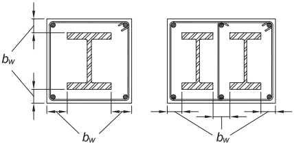
Figure description:
Key Information:
- Subject: Structural diagrams for effective widths ( used in shear strength calculations for encased composite columns.
- Components:
- Steel Core: Hatched I-shaped structural steel sections.
- Concrete Encasement: Outer rectangular boundary.
- Reinforcement: Longitudinal bars (circles and transverse ties/hoops (perimeter lines.
- Configurations:
- Single Section (Left: is defined as the concrete cover distance from the outer face of the column to the face of the steel flange in both transverse directions.
- Multiple Sections (Right: includes the outer concrete cover distances and the interior spacing between the two steel sections.
Fig. C-D1.1. Effective widths for shear strength calculation of encased composite columns.
The minimum area of transverse reinforcement requirement in Equation D1-8 is based on a similar provision in ACI 318, Chapter 18, except that the required area of the transverse reinforcement is reduced to take into account the steel core. The required area of the transverse reinforcement in Equation D1-8 and related detailing provisions for the transverse reinforcement are waived if the steel core of the composite member can alone resist the expected, arbitrary point in time, gravity load on the column because additional confinement of the concrete is not necessary if the steel core can inhibit column failure under gravity loading after an extreme seismic event. The load combination of is based upon a similar combination proposed as loading criteria for structural safety under fire conditions (Ellingwood and Corotis, 1991).
The requirements for composite columns in composite special moment frames (C-SMF) are based on similar requirements for steel and reinforced concrete columns in SMF (FEMA, 2009a; ICC, 2021). For additional information, see Commentary Section E3 and ASCE/SEI 7.
The strong-column/weak-beam concept follows that used for steel and reinforced concrete columns in SMF. Where the formation of a plastic hinge at the column base is likely or unavoidable, such as with a fixed base, the detailing should provide for adequate plastic rotational ductility. For seismic design category E, special details, such as steel jacketing of the column base, should be considered to delay spalling and crushing of the concrete.
Closed hoops are required to ensure that the concrete confinement and nominal shear strength are maintained under large inelastic deformations. The transverse reinforcement detailing requirements are equivalent to those for reinforced concrete columns in SMF. The transverse reinforcement provisions are considered to be conservative because composite columns generally will perform better than comparable reinforced concrete columns with similar confinement; however, the spacing of the transverse reinforcement must meet the limit to restrain buckling of the load-carrying longitudinal reinforcing bars. Further research is required to determine reduced transverse reinforcement requirements for composite columns. It should be recognized that the closed hoop and cross-tie requirements for C-SMF may require special details such as those suggested in Figure C-D1.2 to facilitate the placement of the reinforcement around the steel core. Transverse reinforcement, typically consisting of cross ties and closed hoops, are required to be anchored into the confined core of the column to provide effective confinement.
The transverse reinforcement and concrete cover are generally considered to provide sufficient confinement to the encased steel section for typical conditions, which is why the Specification does not impose any limits on width-to-thickness ratios for encased steel sections. However, in unusual composite column configurations, which may arise in megacolumns where built-up steel sections with slender elements occur close to the face of the column, it is suggested to either (1) limit the width-to-thickness ratios on encased steel sections to 1.4 times the limits imposed on highly ductile steel members in Table D.1.1 or (2) detail the transverse or other reinforcement (e.g., welded studs or anchor bars) to resist local buckling of the encased steel section.
D1.4c Filled Composite Columns
The basic requirements and limitations for detailing and determining the design strength of filled composite columns are the same as those in Specification Chapter I.
D1.5 Composite Slab Diaphragms
In composite construction, floor and roof slabs typically consist of either composite or noncomposite metal deck slabs that are connected to the structural framing to provide an in-plane composite diaphragm that collects and distributes seismic loads. Generally, composite action is distinguished from noncomposite action on the basis of the out-of-plane shear and flexural behavior and design assumptions.
Composite metal deck slabs are those for which the concrete fill and metal deck work together to resist out-of-plane bending and out-of-plane shear due to vertical floor and roof loads. Design procedures for determining flexural and shear strength and codes of practice for such slabs are well established (ASCE, 1991a, 1991b; AISI, 2016; SDI, 2001, 2007, 2017).
Noncomposite metal deck slabs are one-way or two-way reinforced concrete slabs for which the metal deck acts as formwork during construction but is not relied upon for composite action. Noncomposite metal deck slabs, particularly those used as roofs, can be formed with metal deck that is capable of carrying all vertical loads and is overlaid with insulating concrete fill that is not relied upon for out-of-plane strength and stiffness. The concrete fill inhibits buckling of the metal deck, increasing the in-plane strength and stiffness of the diaphragm over that of the bare steel deck.
The diaphragm plays a key role in collecting and distributing seismic loads to the seismic force-resisting systems, and its design requires careful attention to establishing proper load paths and coherent detailing (Sabelli et al., 2011). In some cases, loads from other floors should also be included, such as at a level where a change in the structural stiffness results in redistribution. Recommended diaphragm (in-plane) shear strength and stiffness values for metal deck and composite diaphragms
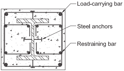
Figure description:
Subject: Cross-section of an encased composite column (Fig. C-D1.2.
Key Components:
- Central Steel Section: An I-shaped structural steel core.
- Concrete Encasement: Surrounds the steel core and reinforcement.
- Load-carrying bars: Longitudinal reinforcement bars positioned at the corners and edges of the column.
- Restraining bars: Internal longitudinal reinforcement bars secured by transverse ties.
- Steel anchors: Connectors welded to the web and flanges of the steel core to ensure composite action with the concrete.
- Reinforcement Ties: A perimeter closed hoop (outer tie and internal transverse hoops/ties that constrain the longitudinal bars and steel core.
Fig. C-D1.2. Example of a closed hoop detail for an encased composite column.
are available for design from industry sources that are based upon tests and recommended by the applicable building code (SDI, 2001, 2007, 2015, 2017). In addition, research on composite diaphragms has been reported in the literature (Easterling and Porter, 1994).
As the thickness of concrete over the steel deck is increased, the shear strength can approach that for a concrete slab of the same thickness. For example, in composite floor deck diaphragms having cover depths between 2 in. (50 mm) and 6 in. (150 mm), measured shear stresses on the order of (where is in units of psi) have been reported. In such cases, the diaphragm strength of concrete metal deck slabs can be conservatively based on the principles of reinforced concrete design (ACI, 2019) using the concrete and reinforcement above the metal deck ribs and ignoring the beneficial effect of the concrete in the flutes.
Alternatively, it is permitted to calculate the diaphragm shear strength per AISI S310 (AISI, 2020), which contains provisions specifically for concrete on metal deck diaphragms. The procedure for calculating diaphragm shear strength in AISI S310 has been calibrated against a set of tests on unreinforced concrete on metal deck specimens. As such, it does not explicitly include reinforcing steel strength, but it captures the shear strength of the unreinforced diaphragm more accurately than the approach using ACI 318 described in the foregoing discussion.
Shear forces are typically transferred through welds and/or shear anchors in the collector and boundary elements. Where concrete fill is present, it is generally advisable to use mechanical devices such as steel headed stud anchors to transfer diaphragm forces between the slab and collector/boundary elements, particularly in complex shaped diaphragms with discontinuities. However, in low-rise buildings without abrupt discontinuities in the shape of the diaphragms or in the seismic force-resisting system, the standard metal deck attachment procedures may be acceptable.
D1.6 Built-Up Structural Steel Members
Shapes and plates may be joined to form built-up shapes where the combined shape behaves as an integral member for the magnitude and type of loading expected. ANSI/AISC 358 provides direction for built-up I-shapes and box columns when forming part of moment connections using prequalified connections. Section F2 provides direction for built-up diagonal braces. Section F3 provides direction for built-up I-shaped and built-up box sections used as links.
Other systems may use built-up members composed of joined plates and/or shapes provided that their connections are designed for the anticipated forces. Where inelastic deformation is expected in a member during a significant earthquake, the connections between elements shall be based on the forces due to that inelastic force level. The basis of design section in the system chapters typically indicates when inelastic deformation is expected and in which members or elements it occurs.
For example, an SCBF diagonal brace is typically required to be connected for its expected axial tension strength, . Furthermore, connections must accommodate brace buckling; therefore, the direction of brace buckling must be determined.
Interconnection of brace elements must address both the magnitude of load and the direction of loading.
The connection design strength requirement of diagonal braces in an ordinary concentrically braced frame (OCBF) is typically governed by forces arising from the load combinations including the overstrength seismic load. These end connection forces can therefore be used to determine the interconnection between the elements. Brace end gussets are not required to be designed for buckling in- or out-of-plane.
For moment frames subjected primarily to flexure, the horizontal shear between elements is a function of the vertical shear at the connection to the column face. The system chapters provide direction to determine this force. For example, Section E1 provides direction to determine the shear in the beam at the column face. This shear force can be used to determine the horizontal shear force between the flanges and web. Connections between elements of columns in moment frames must also be designed both for the horizontal shears between floors and for the high horizontal shear in the column panel zone.
Where protected zones are specified, inelastic deformation is typically expected at that location. An example is the protected zone in a moment-frame beam near the column face. The connection should develop the strength of the weaker element, typically the beam web. This can be accomplished by complete-joint-penetration groove welds or by two-sided fillet welds proportioned to develop the expected strength of the weaker element. Note that the fillet weld option is not permitted for built-up shapes in moment connections governed by ANSI/AISC 358. An example of where fillet welds are permitted is in the protected zone of a special cantilever column systems column per Section E6.