F2.1 Scope
Concentrically braced frames (CBF) have centerlines of members intersecting at points, thus forming a vertical truss system with members subjected primarily to axial loads. A few common types of CBF are shown in Figure C-F2.1, including V-braced (or inverted V-braced), X-braced, and diagonally braced. Special concentrically braced frames (SCBF) are CBF with capacity-based design requirements added
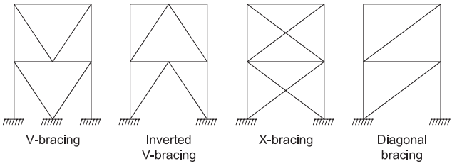
Figure description:
Concentric Bracing Configurations
The image illustrates four types of vertical truss systems for concentrically braced frames (CBF:
- V-bracing: Diagonal members converge to a single point at the center of the bottom horizontal beam or foundation.
- Inverted V-bracing: Diagonal members converge to a single point at the center of the top horizontal beam.
- X-bracing: Two diagonal members cross within each story to form an "X" shape.
- Diagonal bracing: A single diagonal member spans corner-to-corner within each story of the frame.
Fig. C-F2.1. Examples of concentric bracing configurations.
to ensure that the brace is the primary yield mechanism in buckling, tensile yield, and post-buckling deformation and that the brace develops its full resistance and inelastic deformation capacity.
F2.2 Basis of Design
SCBF requirements enhance ductility over that achieved by OCBF and frames designed with with no special design requirements. During severe earthquakes, bracing members in SCBF are subjected to large inelastic deformations in cyclic tension and compression with significant secondary yielding in gusset-plate connections and adjacent beams and columns. The buckling deformation of the brace buckling causes formation of flexural plastic hinges in the brace and gusset plates, with local inelastic deformation in adjacent beam and column members. Braces in typical CBF can be expected to yield and buckle at rather moderate story drifts of about 0.3 to , and braces could undergo post-buckling axial deformations many times their initial yield deformation. The braced frame must be properly detailed to achieve these deformations.
Damage observed from past earthquakes and laboratory tests of CBF with little consideration of ductile member design and detailing has generally resulted in limited ductility and corresponding brittle failures, which are usually manifested in the rupture of connections or bracing members. Bracing that does not meet compactness requirements results in severe local buckling, which imposes a high concentration of flexural strains at the location of buckling and ultimately provides little inelastic deformation capacity. Large story drifts that result from early brace ruptures can impose excessive ductility demands on the beams, columns, and connections.
Research has demonstrated that CBF, with proper configuration, member design, and detailing, can possess ductility far in excess of that previously exhibited by such systems (Goel, 1992a, 1992b; Tremblay, 2001; Lehman et al., 2008; Roeder et al., 2011). SCBF design requirements are based on those research developments.
Previous requirements for concentrically braced frames sought reliable behavior by limiting global buckling. Cyclic testing of diagonal bracing systems verified that energy can be dissipated after the onset of global buckling if brittle failures due to local buckling, stability problems, and connection fractures are prevented. When properly detailed for ductility as prescribed in the Provisions, diagonal braces can sustain large inelastic cyclic deformations without experiencing premature failures.
Analytical and experimental studies (Tang and Goel, 1987, 1989; Hassan and Goel, 1991; Wallace and Krawinkler, 1985) on bracing systems designed in accordance with earlier code requirements for CBF may have brittle failures with little energy dissipation and inelastic deformation capacity.
The more stringent design and detailing requirements for SCBF are expected to produce more reliable performance when subjected to cyclic deformation demands imposed by severe earthquakes. As a result, model building codes have reduced the design load level below that required for OCBF.
F2.3 Analysis
Prior to the 2010 Provisions (AISC, 2010b), the expected nonlinear behavior of SCBF was addressed through a series of design rules that defined required strengths of elements superseding those derived using elastic elements; these included the following:
- (a) Forces for beams in V- and inverted V-braced frames
- (b) Forces for the design of brace connections
- (c) Forces for column design
These design rules were intended to approximate forces corresponding to inelastic response without requiring an inelastic analysis. While these requirements addressed the most important shortcomings of elastic analysis, they had several major deficiencies that motivated development of the current SCBF provisions.
While SCBF are typically designed based on an elastic analysis, their expected behavior includes significant nonlinearity due to brace buckling and yielding, which is anticipated in the maximum credible earthquake. SCBF system ductility can only be achieved if the beams, column, and connections were able to develop the expected resistance of the brace and sustain this resistance throughout its inelastic deformation. Thus, there is a need to supplement the elastic analysis in order to have an adequate design.
The required strength of braces is typically determined based on the analysis required by ASCE/SEI 7. The chosen brace size is then evaluated to determine its expected tensile, buckling, and post-buckling resistance, which is used to design the beams, columns, and connections adjoining the brace. Tests have shown that typical bracing members demonstrate a minimum residual post-buckling compressive strength of about of the initial compressive strength (Hassan and Goel, 1991). For SCBF system behavior, elastic analysis does not accurately reflect performance during extreme earthquakes. Research has developed good nonlinear models with fiber elements to model nonlinear earthquake response (Hsiao et al., 2012; Tremblay, 2001), and the results are limited to the acceleration record analyzed. Rather than requiring nonlinear analysis or developing new and complicated design rules to address system response, a simple explicit consideration of the inelastic behavior by requiring a plastic-mechanism analysis and the expected brace forces is employed.
The first-mode of deformation is considered when determining whether a brace is in compression or in tension; that is, as shown in Figure C-F2.2, the columns are considered to be inclined in one direction rather than in reverse curvature. Consideration must also be given to the behavior when the columns are inclined in the opposite direction. Where frames intersect, loading on the shared column should address the development of these forces in both frames.
Consistent with previous editions of these Provisions, when maximum axial forces are calculated for columns, the engineer is permitted to neglect the flexural forces that result from the design earthquake displacement. This permits straightforward determination of seismic forces. The analysis requirements utilize the expected strengths of braces in tension and compression.
Because the compression behavior of braces differs substantially from the tension behavior, two separate analyses are required:
- (1) An analysis in which all braces have reached their maximum forces
- (2) An analysis in which tension braces are at their maximum strength level and compression braces have lost a significant percentage of their strength after buckling
The Provisions require design of columns to resist forces corresponding to the development of the full plastic mechanism (i.e., yielding and buckling of all braces), unless a nonlinear analysis in accordance with Section C3 demonstrates that a lower force can be used with sufficient reliability. Previous editions allowed the use of the overstrength seismic load in lieu of the full capacity of the connecting braces, based on the expectation of reduced likelihood of simultaneous yielding at multiple floors. Unfortunately, research indicates that the reduction is less dramatic than anticipated and may not be significant for certain building configurations (Richards, 2009).
Section F2.3, Exception (b)(1), refers to establishing a limit on the brace force demand based on the resistance of the foundation to overturning uplift. This is conceptually similar to language in other sections of the Provisions, such as Section F2.6c.1(b) where it is permitted to determine the maximum load effect that can be transferred to the brace by the system. The Commentary to Section F2.6c.1 provides guidance that limits this relief to spread footing foundations where a reasonable estimate of uplift capacity can be estimated. It should be noted that this limitation implies that the braced frame will go into a rocking mode that differs significantly from the response
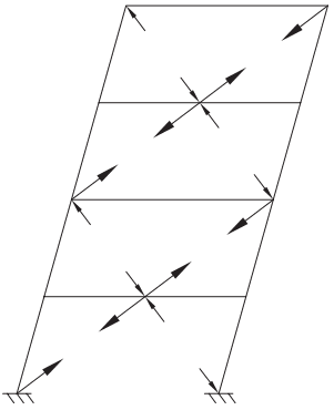
Figure description:
Key Information:
- Entity: A four-story braced frame structural schematic showing an anticipated mechanism under lateral load.
- Deformation: The entire frame is tilted (swaying to the right.
- Force Distribution:
- Arrows: Represent internal axial forces in the diagonal braces and frame members.
- Compression/Tension: Pairs of arrows pointing toward each other indicate compression; arrows pointing away from each other indicate tension.
- Mechanism: Illustrates a rocking response where the frame moves as a unit, influencing the force demand on braces and foundations.
- Support: The base is shown with fixed ground connections.
Fig. C-F2.2. Anticipated braced frame mechanism.
considered in the development of the provisions of this system. While limiting the force on braced frame members, rocking response will cause local rotation demands in connections and beam members adjacent to the braced bays that can become large, depending on the amount of uplift displacement. Detailing of these connections and members to accommodate such rotations should be considered.
Section F2.3, Exception (d), will allow limited yielding of the beam of V- and inverted V-braced frames. Research by Roeder et al. (2019, 2020) shows that limited yielding of the beam will reduce the maximum tensile force of the brace, increase the inelastic deformation capacity of the braced frame prior to brace fracture and deterioration of lateral resistance, increase the fracture life of the brace, and result in limited inelastic vertical deflection of the beam. Columns and brace connections must still be designed for the full expected tensile force of the brace, , because any overdesign of the beam will increase the tensile forces in the brace. Further, the beam-to-column-togusset connection results in a fully restrained connection, and the beam is therefore designed considering a possible hinge adjacent to the edge of the gusset plate at the beam-column connection. Equilibrium requires that the column and beam-to-column connection must be able to able to develop the flexural capacity of the beam.
F2.4 System Requirements
F2.4a Lateral Force Distribution
This requirement attempts to balance the tensile and compressive resistance across the width and breadth of the building because the buckling and post-buckling strength of the bracing members in compression can be substantially less than that in tension. Good balance helps prevent the accumulation of inelastic drifts in one direction.
An exception is provided for cases where the bracing members are sufficiently oversized to provide essentially elastic response. It is envisioned that such an exception would apply to a small number of braces in the structure. It is generally preferable to have braces sized in proportion to their required strength. Where braces have vastly different overstrengths, the inelastic demands may be concentrated and amplified in a small number of braces.
The 2022 Provisions revised the previous requirement to include a specific check to ensure that the system (neglecting the exempted frames) has a minimum strength. Design in accordance with ASCE/SEI 7 (ASCE, 2022) neglecting these frames ensures that torsional effects are considered; torsional effects may be most significant if only one exempted frame is eliminated. This prevents the design of a system predominated by exempted frames. The limits placed on the exempted frames were incorporated for consistency with the ASCE/SEI 7 requirements for redundancy rather than based on a reliability study.
F2.4b V- and Inverted V-Braced Frames
V- and inverted V-braced frames exhibit a special problem that sets them apart from other configurations. With these configurations, the compression brace buckles and its force decreases, while the tension brace force continues to increase up to the point of yielding. This causes unbalanced forces that must be resisted by the intersected members and their connections.
Two-story X- and zipper-braced frames as illustrated in Figure C-F2.3 can be designed to alleviate these concerns or to distribute the increase in post-elastic axial loads to beams at other levels. It is possible to design two-story X-braced and zipper frames to discourage single-story mechanisms. For more information on these configurations, see Khatib et al. (1988), Yang et al. (2008), and Tremblay and Tirca (2003).
Section F2.3, Exception (d), also reduces the unbalanced force caused by tensile and post-buckling deformation of braces by permitting limited yielding of the beam.
Bracing connections should be configured so that beams or columns of the frame are not interrupted because continuous beams are necessary to support any gravity load and to improve the out-of-plane stability of the bracing system at those connections.
Adequate lateral bracing at the brace-to-beam intersection is also needed to prevent adverse effects of possible lateraltorsional and axial buckling of the beam. The stability of this connection is influenced by the flexural and axial forces in the beam, as well as by any torsion imposed by brace buckling or the post-buckling residual out-of-straightness of a brace. The bracing requirements in the Specification were judged to be insufficient to ensure the torsional stability of this connection; therefore, a requirement based on the moment due to the flexural strength of the beam is imposed.
F2.4c K-Braced Frames
K-bracing is prohibited entirely for SCBF because it is considered undesirable to have columns that are subjected to unbalanced lateral forces from the braces, which may contribute to column failures.
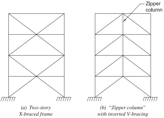
Figure description:
- (a Two-story X-braced frame: A structural diagram showing diagonal braces forming an 'X' pattern across two story levels.
- (b "Zipper column" with inverted V-bracing: A structural diagram featuring chevron-style inverted V-bracing. A vertical "Zipper column" connects the apexes of the braces across successive floors.
- Key Entities: Diagonal braces, horizontal floor beams, vertical columns, and ground supports.
Fig. C-F2.3. Types of braced frames.
F2.4d Tension-Only Frames
Tension-only braced frames are not permitted for SCBF because requirements have not been developed for use with braces that only act in tension.
F2.4e Multi-Tiered Braced Frames
Multi-tiered braced frames (MTBF) are braced frames with two or more tiers of bracing or bracing panels between horizontal diaphragm levels or locations of out-of-plane support. MTBF are common in tall single-story building structures when it is not practical to use single bracing members spanning from roof to foundation levels. As shown in Figure C-F2.4, they can be built using various bracing configurations and have more than one bay. In industrial applications, braced frames used to longitudinally brace crane runways or trussed legs supporting equipment, such as conveyors, form MTBF. They are also used in multistory buildings with tall story heights, such as stadia or concert halls. MTBF columns are typically I-shaped members oriented such that out-of-plane buckling is about the strong axis and in-plane weak-axis buckling occurs over a reduced length. Along braced lines, gravity columns can be horizontally tied at every strut level to benefit from the shorter in-plane buckling length, as is often seen along exterior walls.
Contrary to conventional braced frames in multistory applications, there are no floor diaphragms to laterally brace the columns out of the plane of the frame at every tier level where braces intersect with the columns. Forces inducing out-of-plane deformations of the columns during a seismic event may affect their out-of-plane stability and must be considered in design. These include out-of-plane forces resulting from imperfections at the location of points of intersection of members carrying axial loads or from out-of-plane buckling of the braces. Such effects can affect more slender columns not subjected to other lateral loads, which is the case for columns of interior braced frames not subjected to transverse wind loading. Struts in V- or inverted V-bracing are typically laterally unbraced and must be proportioned to maintain their out-of-plane stability when subjected to twisting arising from brace buckling. The requirement of Section F2.5a that struts satisfy the requirements for moderately ductile members may make V-bracing or inverted V-bracing configurations impractical.
Between struts or points of lateral support, the columns must also resist the effects of out-of-plane forces due to the mass of the structure and supported items in combination with the forces obtained from the analyses required in this section. While the consideration of forces in multiple directions and from multiple sources is a design requirement for all seismic force-resisting systems, it can be particularly critical for multi-tiered braced frame systems.
Inelastic response of MTBF also results in additional in-plane demands that may endanger the frame stability. In particular, unbalanced horizontal loads develop at brace-to-column intersecting points after buckling of the compression braces, which could result in significant in-plane bending moments in the columns. Brace yielding and buckling in MTBF tend to develop progressively along the frame height, which can lead to nonuniform drifts in the bracing panels and, thereby, additional in-plane flexural demands on the columns. Unbalanced horizontal brace forces can be effectively resisted by introducing horizontal struts at tier levels; however, bending moments from nonuniform brace yielding must be resisted by the columns. Axial compression combined with in-plane and out-of-plane bending can lead to column flexural-torsional buckling due to initial imperfections and inelasticity effects. Columns must also have minimum in-plane flexural stiffness to prevent excessive drifts that could lead to premature brace fracture. Contrary to other bracing systems, column bending demands must therefore be explicitly considered in design to achieve satisfactory seismic performance and requirements have been incorporated in the Provisions to assess and properly address this demand and other aspects specific to MTBF.
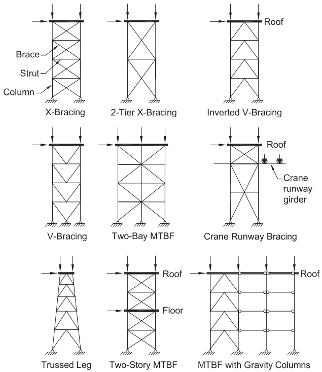
Figure description:
The image illustrates nine typical Multi-Tiered Braced Frame (MTBF configurations used in structural engineering.
Key Entities and Components
- Structural Elements: Columns, braces, struts, roof levels, and floor levels.
- Loading: Indicated by vertical arrows (gravity loads and horizontal arrows (lateral/seismic loads at the top or intermediate levels.
- Foundations: Pinnned supports at the base of each column.
MTBF Configurations
- X-Bracing: Standard multi-tier frame with X-shaped diagonal braces in every tier.
- 2-Tier X-Bracing: A taller single tier of X-bracing spanning two levels.
- Inverted V-Bracing: Braces form a chevron shape pointing upward.
- V-Bracing: Braces form a V-shape pointing downward.
- Two-Bay MTBF: Multi-tier X-bracing spanning across two horizontal bays.
- Crane Runway Bracing: MTBF supporting a crane runway girder with associated crane loads.
- Trussed Leg: A tapered frame configuration narrower at the top.
- Two-Story MTBF: A configuration featuring an intermediate floor level between tiers.
- MTBF with Gravity Columns: A braced bay connected horizontally to adjacent columns that only carry gravity loads.
Fig. C-F2.4. Typical MTBF configurations.
In each braced frame, the story shear in every tier must be resisted by braces acting in tension and compression to ensure that the frame will exhibit a symmetrical inelastic response dominated by braces acting in tension in each direction. Horizontal struts are required at all tier levels to resist the unbalanced horizontal loads induced at brace-to-column connection points after brace buckling. In the absence of a strut, the unbalanced horizontal force would impose significant in-plane flexural demand on the column that could lead to column buckling, as is the case in K-braced frames. Figure C-F2.5 illustrates this behavior. After brace buckling, the struts permit the lateral loads to be transferred over the entire story height, mainly through truss action involving tension-acting braces and struts in compression. Maximum compression in struts is therefore determined from analysis, as discussed in Section F2.3 case (b) when braces in tension are assumed to resist forces corresponding to their expected strength and braces in compression are assumed to resist their expected post-buckling strength.
Upon buckling and subsequent straightening when reloaded in tension, bracing members impose bending moments on their connections and other members framing into the connections. When the braces are detailed to buckle out-of-plane, out-of-plane and torsional moments are imposed on the columns. These two moments are, respectively, the vertical and horizontal components of a moment equal to the expected flexural resistance of the brace (see out-of-plane brace buckling in Figure C-F2.6). If brace connections are detailed to accommodate ductile inelastic rotations, this moment can be limited to times the connection nominal flexural resistance. It is noted that braces buckling out-of-plane do not induce out-of-plane transverse forces at brace-to-column connections, and the moments at work points can be taken as the moments corresponding to the flexural resistance of the braces or brace connections, depending on which one governs. Out-of-plane moments must be resisted by the columns, whereas torsional moments would typically be resisted by the struts bending in the horizontal plane (struts are used to restrain columns against torsion— see Figure C-F2.6).
When braces and their connections are detailed for in-plane buckling, in-plane moments are imposed on the columns and struts because of brace buckling (see in-plane brace buckling in Figure C-F2.6). These moments can be resisted by the columns or the struts, or a combination thereof, depending on the connection details
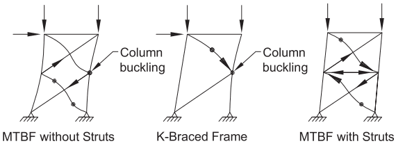
Figure description:
The image illustrates the structural behavior and buckling modes of different bracing configurations in Multi-Tiered Braced Frames (MTBF.
Key Entities and Details:
- MTBF without Struts: Shows global column buckling. The lack of horizontal members between tiers allows the columns to buckle over a greater height.
- K-Braced Frame: Demonstrates column buckling at the mid-height connection point where braces meet the column.
- MTBF with Struts: Shows the inclusion of horizontal strut members. These members brace the columns laterally, forcing buckling into smaller, individual tier segments and distributing internal forces.
- Loading: All frames are subjected to vertical (axial loads on columns and horizontal (lateral shear loads.
- Buckling Indicators: Curved lines and black dots represent the buckled shape and plastic hinge/buckling points of columns and braces.
Fig. C-F2.5. Role of strut members in MTBF.
and relative member stiffness. Connections of braces buckling in-plane are generally detailed such that plastic hinging forms in the braces next to the connections. In this case, the moment demand can be high and impact the columns as it corresponds to the brace expected flexural strength. That demand can be significantly reduced by adopting a knife-plate connection detail in which inelastic rotation occurs through plate bending or by providing an unstiffened gusset connection to the web of I-shaped columns such that the flexibility of the column web accommodates the rotations associated with brace buckling. As for out-of-plane brace buckling, moments at column centerlines can be taken equal to those developing in the braces or brace connections.
In V- and inverted V-bracing, the struts also act as beams resisting the unbalanced vertical loads arising from the braces after brace buckling. In the absence of floor diaphragms at tier levels, lateral stability of the beams can be achieved by providing beams with sufficient strength and stiffness against twisting, as recommended for V- and inverted V-bracing. As stated previously, providing beams with sufficient strength and stiffness that also meet the requirements for moderately ductile members may not be practical for certain configurations. In the case of braces buckling out-of-plane, additional torsion is induced that must be considered in design.
Bracing panels in MTBF act in series between the foundation and the roof levels, or between stories in multistory applications. Recent research (Imanpour et al., 2013) has shown that brace buckling and yielding typically develops progressively along the frame height, which results in nonuniform tier drifts inducing in-plane bending moments in the columns. This behavior is illustrated in Figure C-F2.7 for a uniform four-tiered inverted V-braced frame. As shown, bending is more pronounced in a tier
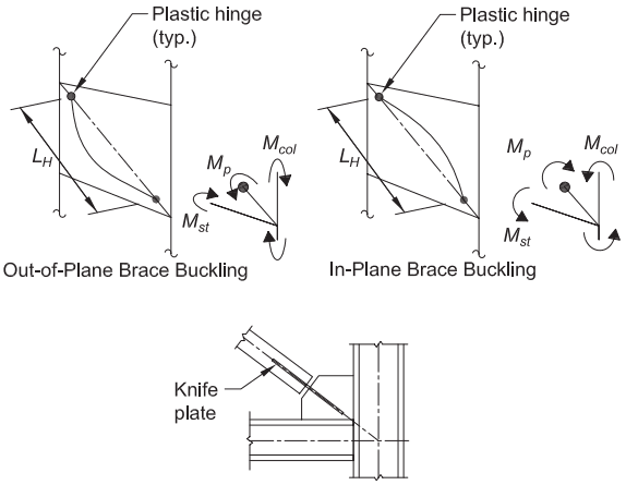
Figure description:
-
Entities:
- Out-of-Plane Brace Buckling: Diagram showing brace deformation perpendicular to the frame plane.
- In-Plane Brace Buckling: Diagram showing brace deformation within the frame plane.
- Plastic Hinge (typ.: Points of concentrated rotation in the buckled braces.
- Knife Plate: Connection detail at the brace-to-column/beam junction.
-
Structural Parameters & Moments:
- : Distance between plastic hinges.
- : Plastic moment capacity at the hinge.
- : Structural moment at the brace connection.
- : Induced bending moment in the column.
-
Context: The diagrams illustrate forces and moments induced in multi-tiered braced frames (MTBF when braces undergo buckling, necessitating column design for in-plane bending.
Fig. C-F2.6. Forces induced by buckling of the braces.
where the brace tension yielding has developed, causing relatively larger drifts and degradation of the compression brace strength in the post-buckling range, while brace tension yielding has not been triggered yet in an adjacent tier. During an earthquake, this scenario occurs in sequence, starting from the weakest tier and propagating in the frame until brace tension yielding has developed in all tiers. The combination of axial compression and bending in the columns may cause in-plane flexural instability of the columns before a complete plastic mechanism is reached where all braces have yielded in tension and attained their post-buckling strength in compression. This behavior is more pronounced in frames with different tier heights or with variability in strength between tiers. Similar response is, however, observed in frames with identical tiers due to unavoidable variability in member strength properties, imperfections, and boundary conditions between tiers.
Section F2.3 includes a third analysis case to assess the flexural demand imposed on multi-tiered special concentrically braced frame (MT-SCBF) columns as brace inelastic response progresses along the frame height. For simple frames, column moments and axial loads can be determined by manual calculations, as is done for Section F2.3 analysis cases (a) and (b). For more complex MT-SCBF configurations, nonlinear static pushover analysis can be used to capture the expected sequence of brace yielding and resulting member forces. In both cases, the analysis is performed until a full brace buckling and yielding mechanism has been reached, corresponding to analysis case (b). Alternatively, column forces can be determined from nonlinear response history analysis. The latter would be more appropriate for taller frames with a large number of tiers as brace yielding may only develop over a fraction of the frame height, resulting in reduced flexural demand.
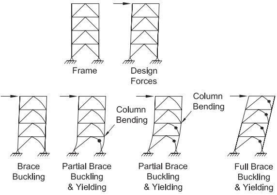
Figure description:
The image illustrates the structural response stages of a Multi-Tiered Special Concentrically Braced Frame (MT-SCBF under lateral load.
Key Entities and Stages:
- Frame: The initial undeformed four-tier braced structure.
- Design Forces: Application of lateral force to the top of the frame.
- Brace Buckling: Initial deformation where the bottom compression brace begins to buckle.
- Partial Brace Buckling & Yielding (Stage 1: Buckling progresses; tension brace yielding begins (marked by dots; column bending occurs at the first-tier junction.
- Partial Brace Buckling & Yielding (Stage 2: Buckling and yielding extend to the second tier; column bending increases.
- Full Brace Buckling & Yielding: The mechanism reaches all four tiers, showing significant lateral drift, full brace yielding (dots on all tension members, and continuous column bending along the frame height.
Fig. C-F2.7. Progression of brace buckling and yielding in MT-SCBF.
Manual calculation is illustrated herein. If nonlinear analysis, static or dynamic, is used, it must be performed in accordance with Chapter C. Guidance on modeling and analysis can be found in Imanpour et al. (2016a, 2016b). The model must account for brace yielding and buckling responses. In static nonlinear analysis, the rate of brace compressive strength degradation must be accentuated to reproduce the conditions expected under cyclic seismic demand (Imanpour and Tremblay, 2014). In nonlinear analysis of uniform frames, brace strengths in one tier must be intentionally reduced by a small amount ( may be appropriate) to reproduce the initiation and subsequent progression of brace buckling and yielding expected in actual frames. Scenarios where brace yielding initiates in the bottom or top tier generally lead to more critical conditions for the columns, as described below.
In well-proportioned frames subjected to increasing lateral loads, all compression braces buckle nearly simultaneously, followed by brace yielding occurring in the tension brace that has the highest stress ratio as the load is increased further and brace force redistribution occurs after brace buckling. In Figure C-F2.8, brace yielding initiates in Tier 1 (the lowest tier). As the brace stretches, drift increases in this tier, which causes bending of the columns. The strength of the compression brace reduces in Tier 1, and the total story shear carried by the brace reduces. Horizontal equilibrium is maintained by shears developing in the columns as they bend. Column flexure reaches a maximum when the tension brace in Tier 2 reaches its expected yield strength, , while the compression brace strength in Tier 1 has reduced to its expected post-buckling strength, . In Tier 2, the compression brace still carries a load close to its expected buckling strength, , and a conservative estimate of the unbalanced brace story shear, , is
(C-F2-1)
The brace force scenarios in Tiers 1 and 2, respectively, correspond to those described in Section F2.3 analysis cases (b) and (a). A numerical example for a two-story
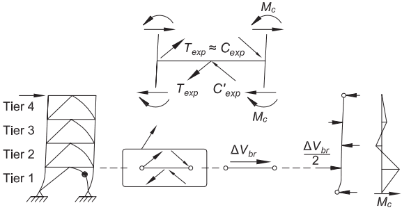
Figure description:
The image illustrates the analysis of unbalanced brace story shear strengths in a Multi-Tiered Special Concentrically Braced Frame (MT-SCBF.
Key Entities and Details:
- Structure: A four-tier braced frame (Tier 1 to Tier 4. Tier 1 is shown undergoing inelastic deformation with a plastic hinge formation.
- Force Variables:
- and : Expected tensile and compressive brace strengths.
- : Reduced expected compressive strength after buckling.
- : Column moments resulting from the unbalanced forces.
- : Unbalanced story shear.
- Force Distribution:
- At the tier level, the unbalanced horizontal force is shown acting on the frame.
- The diagram indicates that the shear is distributed as to the columns.
- Moment Diagram: A moment diagram ( on the far right illustrates the distribution of bending moments along the height of the column due to the tiered unbalanced forces.
Fig. C-F2.8. Unbalanced brace story shear strengths in MT-SCBF.
inverted V-bracing configuration is shown in Figure C-F2.9. In this and the following figures, Cases 1 and 2 correspond to Section F2.3 analysis cases (a) and (b), respectively. The diagram shows the frame resisting the difference between brace story shear strengths in Tiers 1 and 2 (400 kips – 300 kips = 100 kips) when brace yielding initiates in the second level. In this case, the total frame shear is less than the capacity of the braces in the strongest tier because the column shear is in the opposite direction. As shown, the unbalanced brace story shear is resisted equally by the two columns, and moments can be readily obtained from statics. Axial loads induced by the braces can also be easily determined, including the effect of vertical unbalanced brace load at the roof level.
In multi-bay braced frames, unbalanced story shears are resisted by all columns. Gravity columns along braced lines are often tied to MT-SCBF by means of horizontal strut members at tier levels such that their in-plane buckling length is reduced. In this case, a portion of the unbalanced story shear is resisted by the gravity columns, reducing the demand on the braced frame columns. The flexural demand is distributed between braced frame and gravity columns as a function of their relative flexural stiffness properties (Imanpour et al., 2015). Connecting struts must then be designed to carry the axial loads arising from this distribution, and the gravity columns must resist the axial compression plus their share of the flexural demand.
In frames with three or more tiers, the progression of brace yielding and buckling along the height results in a series of scenarios inducing various bending moment demands. This behavior is illustrated in Figure C-F2.10 for a uniform frame for the case where brace yielding initiates in the bottom tier. Moments can be estimated by neglecting column continuity at the top end of the tier in which brace tension yielding is triggered (Case 1). In this simplified model, the column behaves as a simply
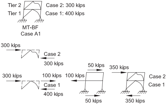
Figure description:
Subject: In-plane flexural demand analysis for a Multi-Tiered Braced Frame (MT-BF, Case A1.
Key Entities and Details:
- Structure: Two-story inverted V-bracing configuration consisting of Tier 1 (bottom and Tier 2 (top.
- Load Cases:
- Case 1: 400 kips
- Case 2: 300 kips
- Force Distribution:
- A 300-kip horizontal force is applied at the top of Tier 2.
- A 400-kip force (Case 1 acts at the Tier 1 level.
- The differential force of 100 kips between cases results in distributed reactions (50 kips each at the top and bottom of the frame.
- The final diagram shows a combined horizontal demand of 350 kips.
- Mechanism: Diagrams illustrate how brace yielding and buckling at different tiers induce varying bending moment demands on the columns.
Fig. C-F2.9. In-plane flexural demand for the columns of a two-story inverted V-bracing configuration (brace yielding in level 2).
supported element resisting its share of the unbalanced brace story shear at the level between tiers where analysis Cases 1 and 2 apply. In this particular case, the unbalanced brace story shear is zero between two consecutive tiers where Case 2 exists. In frames with nonuniform brace strengths, additional forces would need to be considered at these levels.
In design, not all scenarios need to be considered as only one or a few cases will induce critical combinations of axial load and in-plane moment for the columns. For uniform frames, maximum in-plane moments and axial loads may occur in the lowest tier when brace yielding is triggered in that tier after propagation of inelastic response from the top (Figure C-F2.11). Note that out-of-plane moments arising from brace buckling or imperfections must also be considered when verifying the columns, which may affect the critical scenario.
Frames with nonuniform geometries with different brace sizes may result in more complex response, as shown in Figure C-F2.12. Propagation of brace yielding will depend on the relative brace story shear resistance and nonlinear analysis appropriate for this type of frame. Alternatively, column flexural demands can be determined using a suite of linear static analyses with a structural model in which the buckled and yielded braces are removed and replaced by horizontal forces corresponding to the horizontal components of their expected strengths. In each analysis, the horizontal
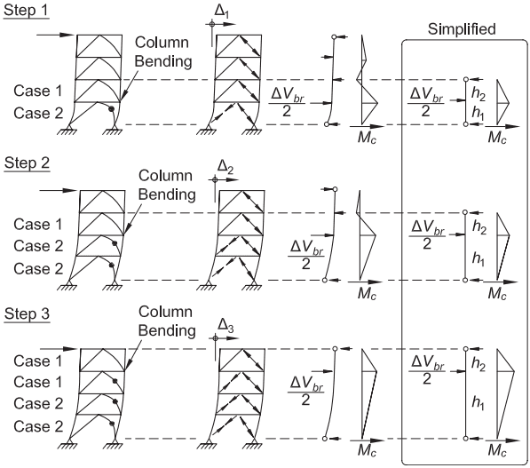
Figure description:
Key Information: Column In-Plane Flexural Demand (Fig. C-F2.10
Entities and Components:
- MT-SCBF (Multi-Tiered Special Concentrically Braced Frame: A four-tiered structural frame subjected to lateral loads.
- Step Sequence (1-3: Illustrates the progressive propagation of brace yielding/buckling up the height of the frame.
- Case 1 & Case 2:
- Case 1: Represents tiers where braces are still elastic or maintaining full strength.
- Case 2: Represents tiers where braces have buckled/yielded, indicated by black dots (plastic hinges and curved members.
- Column Bending (: Shear-induced flexural demand on columns resulting from unbalanced horizontal forces between tiers.
- : The unbalanced horizontal force component at a tier junction due to the difference between yielded and elastic brace strengths.
- Simplified Model: A static representation using a single-span column element with height segments and to calculate moment distribution.
Structural Progression:
- Step 1: Buckling/yielding begins in the bottom tier (; peak moment occurs at the first tier junction.
- Step 2: Propagation to the second tier (; the moment diagram shifts upwards.
- Step 3: Propagation to the third tier (; moment demand is highest at the third tier junction.
Fig. C-F2.10. Column in-plane flexural demand for a uniform MT-SCBF.
load applied at the top of the frame is adjusted such that the tension brace in the tier where the conditions of Section F2.3 analysis case (a) apply. The procedure is illustrated in Figure C-F2.12. Brace yielding initiates in Tier 2 and subsequently develops in Tiers 3 and 1. In the figure, horizontal forces, , correspond to brace story shears determined with the brace expected post-buckling compressive strengths, . Column axial loads are determined by summing the vertical components of the brace strengths.
In-plane bending moments in columns heavily depend on the difference between brace compressive strengths, and , at different tiers. Nonlinear response analysis
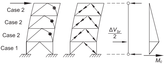
Figure description:
The image illustrates the structural response and bending moment distribution in a multi-tier braced frame undergoing lateral loading.
Key Components:
- Braced Frames: A four-tier frame showing progression of brace yielding.
- Top 3 Tiers (Case 2: Display lateral deformation with dots indicating plastic hinge formation or yielding in the diagonal braces.
- Bottom Tier (Case 1: Remains in an elastic or pre-yield state.
- Internal Forces: Arrows within the middle frame represent tension and compression axial forces acting along the diagonal braces.
- Load Analysis (: A free-body diagram of a column showing an applied lateral force representing the shear difference between tiers.
- Moment Diagram (: A triangular/bilinear distribution chart on the far right showing the in-plane bending moment ( along the height of the column, peaking at the junction between Case 1 and Case 2.
Fig. C-F2.11. Progression of brace yielding from the frame top.
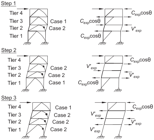
Figure description:
Key Entities and Information:
- Structure: Multi-Tier Special Concentrically Braced Frame (MT-SCBF with four tiers (Tier 1 to Tier 4.
- Process: Three-step progression of brace yielding/buckling starting from the top.
- Yielding Indicators:
- Case 1: Elastic brace behavior.
- Case 2: Yielded/buckled brace behavior (indicated by a dot on the brace.
- Loading and Forces:
- Lateral forces applied at the top.
- : Horizontal component of expected brace strength.
- : Shear force associated with expected post-buckling capacity.
- Progression:
- Step 1: Buckling occurs in Tier 2 (Case 2; other tiers remain Case 1.
- Step 2: Buckling progresses to Tier 3; Tier 1 remains Case 1.
- Step 3: Buckling progresses to Tier 1; Tier 4 remains Case 1.
Fig. C-F2.12 Column in-plane flexural demand from linear static analysis for a nonuniform MT-SCBF.
(Imanpour et al., 2016a, 2016b) has shown that less severe conditions typically exist under actual ground motions, the compression brace forces in the yielded tier being generally higher than , whereas the compression brace in the tier where brace yielding is triggered has lost part of its compressive strength, which results in smaller values of compared to the value predicted by Equation C-F2-1. The conservatism of the approach is deemed to compensate for variability in brace strengths due to uncertainties in material yield strength and brace boundary conditions. Calculations should thus be performed using values of and as specified in the Provisions. When brace buckling response is explicitly modeled in nonlinear dynamic analysis, material variability should also be considered by varying the brace yield strength in tiers where maximum bending moments are obtained. Greater demand is expected when brace sizes or brace inclinations vary along the frame height. Greater demand is also observed when the brace sizes are kept the same even when tier heights are varied. Attention must be paid when configuring the frame geometry and brace sizes to minimize the demand.
Numerical simulations indicate that, in some cases, this in-plane column yielding reduces the out-of-plane flexural buckling strength of the column (Stoakes and Fahnestock, 2013). This reduction is most pronounced when the in-plane column yielding occurs near mid-height of the column, which is the situation in two-tiered frames. However, the deleterious effects of in-plane column yielding on out-of-plane flexural buckling can be mitigated by providing torsional bracing that satisfies the minimum stiffness and strength requirements developed by Helwig and Yura (1999) at every tier level. Torsional bracing of columns can be provided by mobilizing the out-of-plane flexural stiffness of tier-level struts. I-shaped struts oriented such that their webs are in the horizontal plane represent an effective means of providing torsional stiffness and strength through strong-axis bending. Struts must also resist in-plane torsional moments imposed by brace out-of-plane buckling. Strut-to-column connections must be detailed to develop the required strength and stiffness.
Axial forces acting in braces and struts may induce out-of-plane horizontal loading to the columns due to imperfections in the connecting points resulting from column out-of-plane out-of-straightness. The effects of these forces are amplified due to second-order and inelasticity effects resulting from the presence of axial compression load in the columns. Imperfection effects are present under any load combination that includes lateral loads, including seismic loads. They can be evaluated through the direct analysis method with explicit consideration of geometrical imperfections, as described in Specification Chapter C. Alternatively, horizontal notional loads are given in the Provisions that can be applied to account for geometrical imperfection and inelasticity effects. When applying these loads, second-order effects must still be considered using either the direct second-order analysis method or the approximate second-order analysis method where moments are amplified by the factor, as described in Specification Appendix 8. In addition, a maximum value for the amplification factor, , is specified in this section to prevent from using columns exhibiting limited out-of-plane stiffness.
Column shear distortion is the sum of the overall frame drift and the distortion due to column bending, and it is limited to 2%, which is considered reasonable for buckling braces.
F2.5 Members
F2.5a Basic Requirements
Braces buckle under severe seismic loads, and buckling results in formation and substantial rotation of plastic hinges in the brace. Deformation occurs, similar to that which local buckling causes, at the plastic hinges, and large strain concentrations result. Braces with compact elements that meet high ductility requirements are capable of achieving large inelastic deformation and significant inelastic story drifts. Tests have shown that the cross-sectional shape of rectangular hollow structural sections (HSS) with width-to-thickness ratios larger than the prescribed limits make them susceptible to fracture at small inelastic deformations (Goel, 1992a; Hassan and Goel, 1991; Tang and Goel, 1989; Tremblay, 2000; Yang and Mahin, 2005; Lehman et al., 2008). Width-to-thickness ratios of high ductility demand compression elements in bracing members have been set to be at or below the Specification requirements for compact sections in order to assure inelastic deformation capacity during repeated inelastic cycles.
Columns in SCBF also need to satisfy high ductility slenderness limits because their flexural strength and rotation capacity have been shown to be a significant contributor to the stability of SCBF (Tremblay, 2001, 2003). It has also been demonstrated that SCBF can be subjected to significant story drift (Sabelli et al., 2003; Lehman et al., 2008), requiring columns to undergo inelastic rotation.
Enhanced ductility and fracture life of rectangular HSS bracing members can be achieved in a variety of ways. The HSS walls can be stiffened by using longitudinal stiffeners, such as rib plates or small angle sections in a hat configuration (Liu and Goel, 1987). The use of plain concrete infill has been found to be quite effective in reducing the severity of local buckling in the post-buckling range of the member (Liu and Goel, 1988; Lee and Goel, 1987, 1990).
F2.5b Diagonal Braces
The slenderness, , limit is 200 for braces in SCBF. Research has shown that frames with slender braces designed for compression strength behave well due to the overstrength inherent in their tension capacity. Tremblay (2000), Tang and Goel (1989), and Goel and Lee (1992) have found that the post-buckling cyclic fracture life of bracing members generally increases with an increase in slenderness ratio. An upper limit is provided to preclude dynamic effects associated with extremely slender braces.
Closer spacing of stitches and higher stitch strength requirements are specified for built-up bracing members in SCBF (Aslani and Goel, 1991; Xu and Goel, 1990) than for typical built-up members. This is especially critical for double-angle and doublechannel braces that impose large shear forces on the stitches upon buckling. These stitches restrict individual element bending between the stitch points and prevent premature fracture of bracing members. Typical spacing following the requirements of the Specification is permitted when buckling does not cause shear in the stitches. Bolted stitches are not permitted within the middle one-fourth of the clear brace length as the presence of bolt holes in that region may cause premature fractures due to the formation of a plastic hinge in the postbuckling range. Studies also showed that placement of double angles in a toe-to-toe configuration reduces bending strains and local buckling (Aslani and Goel, 1991).
The required strength of bracing members with respect to the limit state of tensile rupture on the net section is the expected brace yield strength, and structural steel materials have expected or average yield strengths that are higher than their specified minimum yield strengths, with some approaching or exceeding the specified minimum tensile strength. No significant reduction of the brace section is permissible for net section evaluation in these cases, and braces may require local reinforcement of their net section. Slotted connections with pipe, square, rectangular, or round HSS braces have a reduced net section at the over-slot of the brace and may require reinforcement (Korol, 1996; Cheng et al., 1998). The net effective area may be based on reinforcement with steel plates welded to the tube (Yang and Mahin, 2005). Braces with two continuous welds to the gusset wrapped around its edge (instead of the more typical detail with four welds stopping short of the gusset edge) performed adequately in the tests by Cheng et al. (1998). However, this practice may be difficult to implement in field conditions, and it may create a potential stress riser that may lead to crack initiation. It is recommended that the connection of the reinforcement to the brace be designed for the strength of the reinforcement on either side of the reduced section.
F2.5c Protected Zones
Protected zones in SCBF include elements that connect braces to beams and columns, such as gusset plates, and expected plastic-hinge regions in the brace.
Figures C-F2.13 and C-F2.14 show the protected zone of an inverted V- and an X-braced frame, respectively. Note that for the X-braced frame, the half-length of the brace is used, and a plastic hinge is anticipated at the center one-quarter of the clear half-length distance.
Beams of V- and inverted V-braced frames designed by Section F2.3 Exception (d) will result in significant yielding in the beam adjacent to the midspan gusset plate. The most economical design of the beams of V- and inverted V-braced frames occurs when a plastic hinge is permitted in the beam adjacent to the beam-column connection, and significant yielding must also be expected adjacent to the corner gusset plates. As a result, protected zones are required for a distance of the beam depth, , from the edge of these gusset plates.
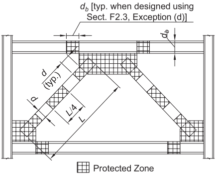
Figure description:
Key Information: Protected Zone of Inverted V-Braced Frame
- Entities: Structural steel frame consisting of columns, horizontal beams, and diagonal "inverted V" braces.
- Protected Zones (Cross-Hatched Areas:
- Brace Members: Four specific zones along the length of each brace, including ends and mid-span locations (marked with dimensions , , and .
- Beam-Brace Connection: A large central zone where the inverted V braces meet the horizontal beam.
- Beam-Column Connections: Zones located at the intersections of the horizontal beams and vertical columns.
- Dimensional Notations:
- : Depth of the beam; defines the horizontal extent of the protected zone on the top beam when designed per Sect. F2.3, Exception (d.
- : Depth of the brace member.
- : Total length of the brace member.
- : Specifies the interval for protected zones along the brace length.
Fig. C-F2.13. Protected zone of inverted V-braced frame.
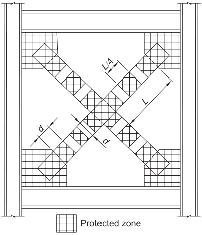
Figure description:
Key Information:
- Subject: Protected zone of an X-braced frame (Fig. C-F2.14.
- Entities:
- Steel Frame: Consists of vertical columns and horizontal beams.
- X-Bracing: Two diagonal members crossing at the center.
- Gusset Plates: Connection points at the four corners where braces meet the frame.
- Protected Zone (Cross-hatched areas:
- Covers the gusset plates and the connection regions of the braces.
- Extends along the diagonal braces at the center intersection for a length of (where is the length between the center and the gusset plate.
- Extends along the diagonal braces at the ends for a distance from the gusset plate.
- Dimensions:
- : Length of the brace segment from center to corner.
- : Distance of the protected zone extending onto the brace from the connection.
Fig. C-F2.14. Protected zone of X-braced frame.
F2.6 Connections
F2.6a Demand Critical Welds
Groove welds at column splices are designated as demand critical because it is believed that their failure may endanger the safety of the frame. Further, inflection points in columns during an earthquake are constantly moving, so the actual forces at column splices during an earthquake are very difficult to predict. Analysis of the frame under code-specified load combinations may show little or no tension will occur at a weld, but such an analysis cannot be considered reliable for the prediction of these demands. Accordingly, to provide a high degree of protection against brittle failure at column splice groove welds, the use of demand critical welds is specified. Partial-joint-penetration (PJP) groove welds are included in this requirement because the unfused portion on the weld makes PJP welds particularly prone to brittle failure.
F2.6b Beam-to-Column Connections
Braced frames are likely to be subjected to significant inelastic drift. Thus, significant end rotation of the brace must be expected, and significant secondary yielding in the adjacent beam and column are likely (Uriz and Mahin, 2004). The provisions allow the engineer to select from three options. The first is a simple connection that has a required rotation defined as 0.025 rad. Along with Part 10 of the AISC Steel Construction Manual (AISC, 2017), Figures C-F2.15 and C-F2.16 illustrate connections proposed for this role (Stoakes and Fahnestock, 2010; McManus et al., 2013). These connections primarily achieve frame rotation through deformation of the bolted gusset between the beam, gusset, and column. Brace end rotations must be accommodated through deformation of the gusset with detailing such as described in Commentary Section F2.6c. Fahnestock et al. (2006) and Thornton and Muir (2008)
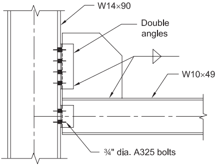
Figure description:
- Figure Description: Engineering diagram (Fig. C-F2.15 of a beam-to-column connection designed to allow rotation.
- Key Entities & Components:
- Column: W14×90 wide-flange section.
- Beam: W10×49 wide-flange section.
- Connection: Double angles bolted to the column.
- Fasteners: 3/4" diameter A325 bolts.
- Gusset Plate: Located between the beam and column, integrated with the double angle connection.
- Welds: Indicated by welding symbols on the gusset and beam interfaces.
Fig. C-F2.15. Beam-to-column connection that allows rotation (Stoakes and Fahnstock, 2010).
propose a connection with frame rotation accommodated by a beam release outside the gusset plate as shown in Figure C-F2.17.
The majority of the connections designed to this first option are hybrids, where the 0.025 rad frame rotation is accommodated by a combination of bending of the frames and deformation of the gusset plate and the beam-column connection (McManus et al., 2013; Uriz and Mahin, 2004; Lehman et al., 2008), and the brace end rotation is accommodated by deformation of the gusset plate.
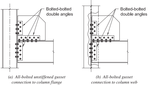
Figure description:
Key Information Title: All-bolted beam-to-column connection that allows rotation.
Entities & Components:
- Column: Structural vertical member (flange and web sections shown.
- Beam: Structural horizontal member.
- Gusset Plate: Connecting element between the beam and column.
- Bolted-bolted double angles: Connectors used at three points:
- Gusset-to-column interface.
- Gusset-to-beam interface.
- Beam-to-column interface.
Connection Types:
- (a Connection to column flange: Features an unstiffened gusset.
- (b Connection to column web: Bolted assembly attached within the column's web area.
Fig. C-F2.16. All-bolted beam-to-column connection that allows rotation (McManus et al., 2013).
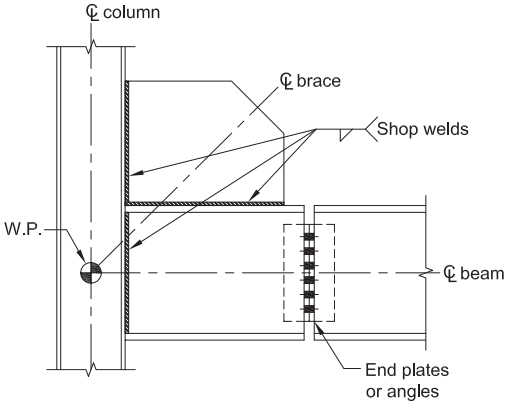
Figure description:
- Type: Structural engineering diagram of a beam-to-column connection allowing rotation.
- Key Entities:
- Column: Vertical member with designated centerline.
- Beam: Horizontal member with designated centerline.
- Brace: Diagonal member with designated centerline.
- Work Point (W.P.: The intersection point of the column, beam, and brace centerlines.
- Shop Welds: Used to attach the gusset plate to the column flange and the top of the beam.
- End plates or angles: Bolted connection between the beam segments to facilitate rotational movement.
Fig. C-F2.17. Beam-to-column connection that allows rotation (Thornton and Muir, 2008).
The second option is a fully restrained moment connection for which the maximum moment can be determined from the expected strength of the connecting beam and column.
The third option is also a fully restrained moment connection. Rather than give a required strength of the connection, this option refers to the prescriptive requirements for one of the OMF connection alternatives.
F2.6c Brace Connections
Many of the failures reported in concentrically braced frames due to strong ground motions have been in the connections. As a result, connections today are capacity designed to develop the full range of expected tensile yield, buckling, and post-buckling resistance and deformation of the brace (Astaneh-Asl et al., 1986; Lehman et al., 2008). Good connection performance can be expected if the effects of brace member cyclic post-buckling behavior are considered. While it is essential that the brace-to-beam-to-column connections be designed to have adequate resistance to meet these Provisions, research has shown that gusset plates should not be designed with excess resistance because overstrength in the gusset plate restrains end rotation of the brace and causes earlier brace fracture (Lehman et al., 2008; Roeder et al., 2011).
Certain references have suggested limiting the free edge length of gusset plates, including SCBF brace-to-beam connection design examples in the AISC Seismic Design Manual (AISC, 2006) and other references (Astaneh-Asl et al., 2006; ICC, 2006). However, the committee has reviewed the testing cited and has concluded that such edge stiffeners do not offer any advantages in gusset plate behavior. There is, therefore, no limitation on edge dimensions in these Provisions.
F2.6c.1 Required Tensile Strength
Braces in SCBF are required to have gross section tensile yielding as their governing limit state so that they will yield in a ductile manner. Local connection failure modes, such as block shear rupture, must be precluded. Therefore, the calculations for these failure modes must use the maximum load that the brace can develop.
The minimum of two criteria, the expected axial tensile strength of the bracing member and the maximum force that could be developed by the overall system, determines the required strength of both the bracing connection and the forces delivered to the beam-to-column connection. This second limit is included in the Provisions for structures where elements other than the tension bracing limit the system strength. Depending on the specific situation(s), there are many ways to determine the maximum force transferred to the connection, including the following:
-
(a) Perform a pushover analysis to determine the forces acting on the connections when the maximum frame capacity, leading to an imminent collapse mechanism, is reached.
-
(b) Determine how much force can be resisted before causing uplift of a spread footing (note that the foundation design forces are not required to resist more than the code base-shear level). This type of relief is not typically applicable to a deep foundation because determining when uplift will occur is difficult to accurately predict.
-
(c) Perform a suite of inelastic time history analyses in accordance with Section C3 and envelop the connection demands.
Calculating the maximum connection force by one of these three methods is not a common practice on design projects. In some cases, such an approach could result in smaller connection demands; however, from a conceptual basis, because the character of the ground motions is not known to any great extent, it is unrealistic to expect that such forces can be accurately calculated. All three approaches rely on an assumed distribution of lateral forces that may not match reality. The third approach is probably the best estimate, but also the most calculation intensive. In most cases, providing the connection with a capacity large enough to yield the member is needed because of the large inelastic demands placed on a structure by a major earthquake.
Bolt slip is not a limit state that must be precluded. The consequences of exceeding this limit state in the maximum credible earthquake are not considered severe if bearing failure and block shear rupture are precluded.
F2.6c.2 Required Compressive Strength
Bracing connections should be designed to withstand the maximum force that the brace can deliver in compression. A factor of 1.1 had been applied to the expected brace strength in consideration of the use of conservative column curve equations in determining this force. This factor was removed in 2016 because the 1/0.877 factor used to determine the expected brace strength in Section F2.3 adequately bounds the maximum anticipated force the brace can deliver.
F2.6c.3 Accommodation of Brace Buckling
Braces in SCBF are expected to undergo cyclic buckling under severe ground motions, forming plastic hinges at their center and at each end. To prevent fracture resulting from brace rotations, bracing connections must either have sufficient strength to confine inelastic rotation to the bracing member or sufficient ductility to accommodate brace end rotations.
For gusset plates designed to develop the end rotation of the brace, the end connections should develop the expected tensile and compressive strengths of the brace and the expected flexural strength of the brace as it transitions from pure compression towards a condition dominated by flexure (Astaneh-Asl et al., 1986). Note that a realistic value of the effective length factor, , should be used to represent the connection fixity.
For brace buckling out of the plane of single plate gussets designed to satisfy Section F2.6c.3(b), weak-axis bending in the gusset is induced by member end rotations. This results in flexible end conditions with plastic hinges at midspan in addition to the hinges that form in the gusset plate. Satisfactory performance can be ensured by allowing the gusset plate to develop minimal restraint plastic rotations. This requires the end of the brace to be held back away from the beam and column so that the gusset can effectively form a plastic hinge as the brace buckles.
The linear clearance zone (Astaneh-Asl et al., 1986; Astaneh-Asl, 1998) provides a linear hinge zone with a length of 2 times the plate thickness. Note that this clear distance is measured from the end of the brace to a line that is perpendicular to the brace centerline, drawn from the point on the gusset plate nearest to the brace end that is constrained from out-of-plane rotation as shown in Figure C-F2.18(a). This clearance model is very effective when tapered gusset plates are employed; however, buckling of the gusset plate may control the design because gussets must be designed to prevent gusset plate buckling prior to member buckling.
More recent research recommended an 8 elliptical clearance zone for corner gusset plates as shown in Figure C-F2.18(b) and a horizontal clearance zone for midspan gusset plates as shown Figure C-F2.18(c) (Roeder et al., 2011).
thickness of gusset plate
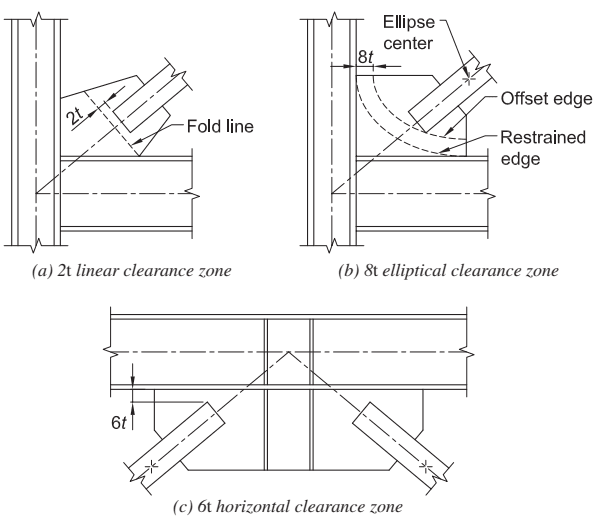
Figure description:
Brace-to-gusset plate requirements for out-of-plane buckling systems:
- : Thickness of the gusset plate.
- (a linear clearance zone: A linear fold line is established with a perpendicular clearance distance of from the end of the brace.
- (b elliptical clearance zone: Uses an elliptical zone defined by an ellipse center, offset edge, and restrained edge. A horizontal clearance of is maintained from the vertical column face.
- (c horizontal clearance zone: A vertical clearance of is provided between the horizontal beam flange and the end of the brace connection on the gusset plate.
Fig. C-F2.18. Brace-to-gusset plate requirement for buckling out-of-plane bracing system.
These clearance models result in thinner gusset plates, which are seldom controlled by gusset plate buckling, and research shows that this may result in increased inelastic deformation capacity. Figure C-F2.19 shows typical overall frame hysteretic behavior of SCBF designed by these methods.
Braces with in-plane buckling may be designed with gusset plate connections that can develop the full flexural resistance and end restraint of the brace, or end rotation of buckling may be permitted with connection details such as those proposed by Tsai et al. (2013), as illustrated in Figure C-F2.20.
Alternatively, connections with stiffness in two directions, such as cross gusset plates, can be designed and detailed to satisfy Section F2.6c.3(a) (Lee and Goel, 1987). Where fixed-end connections are used in one axis with pinned connections in the other axis, the effect of the fixity should be considered in determining the critical buckling axis. However, research has shown that such analysis is imprecise in controlling the direction of brace buckling behavior because initial crookedness and local imperfections may dominate.
F2.6c.4 Gusset Plates
Where a brace frames to a beam-column joint, the stresses on a corner gusset weld are a result of brace axial forces combined with gusset flexure, as the brace buckles, and frame moments (except where moment releases are provided). Accurate prediction of maximum stresses at large drifts is difficult, and early fracture of the welds has been noted in experiments where the welds are designed using the uniform force method and the expected tensile capacity of the brace (Lehman et al., 2008). To forestall such fracture, it is recommended that these welds be designed to develop the plastic capacity of the gusset plate.
Carter et al. (2016) developed such a method, mentioned in the User Note, utilizing a generalized interaction equation recommended by Dowswell (2015). With this method, the weld size can be selected to develop the maximum weak-axis moment occurring in combination with the shear, compression, and strong-axis moment that result on the gusset plate edge from the brace compression force.
F2.6d Column Splices
In the event of a major earthquake, columns in concentrically braced frames can undergo significant bending beyond the elastic range after buckling and yielding of the braces. Even though their bending strength is not utilized in the design process when elastic design methods are used, columns in SCBF are required to have adequate compactness and shear and flexural strength in order to maintain their lateral strength during large cyclic deformations of the frame. In addition, column splices are required to have sufficient strength to prevent failure under expected post-elastic forces. Analytical studies on SCBF that are not part of a dual system have shown that columns can carry as much as 40% of the story shear (Tang and Goel, 1987; Hassan and Goel, 1991). When columns are common to both SCBF and special moment frames (SMF) in a dual system, their contribution to story shear may be as high as 50%. This feature of SCBF greatly helps in making the overall frame hysteretic loops “full” when compared with those of individual bracing members, which are generally “pinched” (Hassan and Goel, 1991; Black et al., 1980). See Figure C-F2.19 for an example of a “full” hysteretic loop associated with the overall frame.
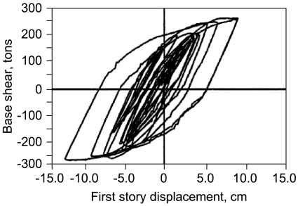
Figure description:
Hysteretic Response Curve Base shear as a function of first story displacement
Base shear vs. First story displacement
Annotations
- Zero displacement line (vertical_line - position: x = 0)
- Zero base shear line (horizontal_line - position: y = 0)
| First story displacement (cm) | Base shear (tons) |
|---|---|
| 0.0 | 0 |
| 1.0 | 100 |
| 2.5 | 190 |
| 1.0 | 50 |
| 0.5 | 0 |
| -1.0 | -100 |
| -2.5 | -180 |
| -1.0 | -50 |
| -5.0 | -225 |
| -2.0 | 0 |
| 1.5 | 190 |
| 5.0 | 240 |
| 6.5 | 250 |
| 5.0 | 150 |
| 3.0 | 0 |
| 0.0 | -160 |
| -4.0 | -240 |
| -8.5 | -260 |
| -5.0 | -100 |
| -3.5 | 0 |
| 1.5 | 200 |
| 5.0 | 245 |
| 8.8 | 260 |
| 7.0 | 160 |
| 4.2 | 0 |
| 1.0 | -150 |
| -5.0 | -250 |
| -10.5 | -270 |
| -13.1 | -275 |
| -8.0 | -200 |
| -4.5 | -100 |
| -3.3 | 0 |
| 0.0 | 185 |
Notes: The chart displays multiple overlapping hysteretic loops showing the cyclic relationship between base shear and story displacement. The data points provided represent the progression of these loops from inner to outer bounds.
Fig. C-F2.19. Base shear versus story drift of an SCBF.
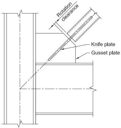
Figure description:
Subject: Structural diagram of a gusset plate connection designed for in-plane rotation.
Key Entities:
- Column: Vertical structural member.
- Beam: Horizontal structural member.
- Gusset plate: Plate connecting the beam, column, and diagonal brace.
- Knife plate: Plate component connecting the diagonal brace to the gusset plate.
- Rotation clearance: A specified gap between the brace member and the gusset plate to allow for rotational movement.
- Diagonal Brace: Structural member connected at an angle to the beam-column joint.
Fig. C-F2.20. Gusset designed for in-plane rotation (Tsai et al., 2013).