E3.2 Basis of Design
Special moment frames (SMF) are generally expected to experience significant inelastic deformations during large seismic events. It is expected that most of the inelastic deformation will take place as rotation in beam “hinges,” with limited inelastic deformation in the panel zone of the column. The beam-to-column connections for these frames are required to be qualified based on tests that demonstrate that the connection can sustain a story drift angle of at least 0.04 rad using the loading protocol specified in Section K2. Other provisions are intended to limit or prevent excessive panel-zone distortion, column hinging, and local buckling that may lead to inadequate frame performance in spite of good connection performance.
Beam-to-column connections in SMF systems are permitted to be fully restrained (FR) or partially restrained (PR). ANSI/AISC 358 prequalification considers the performance of the connection and frame. To permit the use of PR connections in SMF systems, system performance equivalent to SMF systems meeting all of the requirements of Section E3 is required to be demonstrated by analysis. The analysis should evaluate the effect of connection restraint in the elastic and inelastic range on system performance and should demonstrate equivalent performance to systems employing qualifying FR connections. This may be accomplished using FEMA P-795 (FEMA, 2011), which considers the similarity of the hysteretic response of a “substitute” connection—in this case, a PR connection—and a “benchmark” connection, which could be any prequalified connection. ANSI/AISC 358 (AISC, 2022b) has prequalified one PR connection, the Simpson Strong-Tie® Strong Frame® moment connection, for use in SMF. Alternatively, equivalent performance may also be substantiated through analysis conforming to ASCE/SEI 7, Sections 12.2.1.1 and 12.2.1.2 (ASCE, 2022).
Because SMF and IMF connection configurations and design procedures are based on the results of qualifying tests, the parameters of connections in the prototype structure must be consistent with the tested configurations. Chapter K and ANSI/AISC 358 provide further detail on this requirement.
E3.3 Analysis
The strong-column/weak-beam (SC/WB) concept, as defined for planar frames in Section E3.4a, is a capacity-design approach intended to provide for frame columns strong enough to distribute frame (primarily beam) yielding over multiple stories, rather than concentrating inelastic action in column hinging at a single story (weak story). The requirement outlined in Section E3.4a is an approximate and simplified method, in use for several generations of these Provisions, that is deemed to provide the desired performance for planar frames. It should be recognized that other analyses could be used to demonstrate that the desired performance could be achieved—for example, an analysis considering the performance on a story, rather than individual column, basis.
Recognizing that in systems such as SMF, significant yielding of the structure is expected under the design displacements and recognizing that design displacements can occur in any direction relative to the orthogonal axes of the structure, the possible effects of yielding of the structure in both directions simultaneously must be considered in columns that participate in SMF in more than one direction.
ASCE/SEI 7 requires that analyses include the effects of 100% of the design motions in one direction in conjunction with 30% of those in the orthogonal direction. As even the 30% design motion is likely capable of yielding the structure, and considering that the 100% motion may occur in any direction relative to the structure’s axes, it is clear that simultaneous yielding of orthogonal systems is likely and should be considered in the design.
The extent to which simultaneous yielding of orthogonal systems is of concern is a matter of configuration and design. Consider the following examples:
-
(a) An efficiently designed, symmetrical, two-way moment frame with shared columns that conforms with Section E3.4a in each direction independently is subjected to design motions at or near 45° to the structure’s axes. For this case, a story mechanism could occur due to hinging of all columns in a story because of the weakening effects of the unaccounted-for biaxial effects on the columns. In this case, the designer should consider application of the SC/WB analysis in both orthogonal directions simultaneously.
-
(b) A system consisting of multi-bay planar moment frames in each orthogonal direction, intersecting at corner columns only. For this case, demonstration of the desired performance could be shown by an analysis that considers the relative strength of the columns to the beams on a story, rather than individual, basis. Additionally, the bending strength of the corner columns would need to be considered as the column strength was reduced by the orthogonal yielding effects. As a simpler and conservative alternate, the strength of the corner columns could be ignored in calculating the story strength. In either case, the corner column would need to be checked for strength considering the effects of axial force and biaxial bending as required by the Specification.
Other analysis methods could also be considered to confirm the desired performance as described in the following sections.
Column-Tree Method. One approach to get a reasonable estimate of the required strength of columns for ensuring essentially elastic behavior is to consider the equilibrium of the entire column (sometimes called the “column tree”) in its expected extreme deformed condition (Goel and Chao, 2008). For this purpose, the column from bottom to top can be treated as a vertical cantilever with all expected forces acting on it to satisfy equilibrium. The forces will include moments and shears from the yielded beams framing into the column at all floor levels along with gravity loads supported by the column. By assuming an appropriate vertical distribution of lateral inertia forces, and expected moment at the base of the column, the magnitude of the lateral forces can be calculated by using the moment equilibrium equation for the “column tree.” For columns that are part of frames in a single plane (flexural loading about one axis), it is appropriate to take the moment applied by the yielded beams as the probable moment, . Lower values may be justifiable recognizing it is unlikely that beams at all levels within a multistory building will reach this value (Goel and Chao, 2008).
For columns that are part of intersecting frames, the preceding calculation needs to be carried out in two orthogonal planes along the two principal axes of the column. It is highly unlikely that maximum expected moments and corresponding shears in the beams would occur simultaneously along the entire height of the column. Using the plastic moment at the beam ends and the corresponding shear appears to be reasonable to represent the intersecting frames behaving inelastically simultaneously. The bending moments, shears, and axial force in each story in both orthogonal planes can be calculated by statics. The design of the biaxially loaded beam-columns can be carried out by using the Specification. In applying effects, a drift resulting in the yielding of beams in each intersecting frame should be considered. A drift is often a reasonable approximation to achieve this.
Interaction Method. In most building configurations, a seismic force-resisting system can be idealized as a system of planar moment frames, with internal forces being resisted in the plane of the frames. Equation E3-2 utilized in the verification of SC/ WB approximates the full plastic interaction for uniaxial bending. This equation represents the moment capacity of a column reduced due to the effect of an axial force. In the case where a column forms part of two or more intersecting moment frames, it may be necessary to check the SC/WB criteria about both axes of the col- umn. In this situation, Equation E3-2 does not explicitly address biaxial bending and account for the reduction in moment capacity of the column about the axis under consideration due to the moment demand in the column about the orthogonal axis. Equation E3-2 can be modified to include the effect of biaxial bending by similarly assuming a linear interaction, commonly referred to as a "yield surface," as given by Equation C-E3-1:
(C-E3-1)
where
- gross area of column, in.
- plastic moment of the column in the plane of the frame under consideration, kip-in. (N-mm)
- as defined in Section E3.4a, kips (N). In this case, should be determined according to Chapter D by addressing the axial force input from all frames connected to the column.
- Zy = plastic section modulus of the column out of plane of the frame under consideration, in.³ (mm³)
- for LFRD and 1.5 for ASD
In Equation C-E3-1, the subscripts and represent in-plane and out-of-plane section properties of the column, respectively, and do not designate the strong and weak axes of the column. In design, when it is necessary to verify SC/WB about both column axes, the orthogonal section properties of the column will change accordingly.
In the simplest case, can be estimated as , where is the plastic moment of a beam in the out-of-plane frame at the joint under consideration, kip-in. (N-mm).
The linear yield surface given by Equation C-E3-1 is illustrated in Figure C-E3.1. Only one quadrant is shown for brevity.
Equation E3-2 and its biaxial extension, Equation C-E3-1, may provide a conservative estimate of the plastic moment for specific sections. For example, based on classical plastic design theory, the strong-axis plastic moment (taken as the -axis) of a wide-flange section can be taken as Equation C-E3-2:
(C-E3-2)
where is the specified minimum yield stress of the wide-flange section. Similarly, the weak-axis plastic moment (taken as the y-axis) of a wide-flange section can be taken as Equation C-E3-3:
(C-E3-3)
Equations C-E3-2 and C-E3-3 are for cases when no moment about the axis orthogonal to the axis under consideration is present. Several yield surfaces that account for bi-axial bending are discussed in the SSRC Guide to Stability Design Criteria (Ziemian, 2010). For example, a linear equation applicable for a wide-flange section was proposed by Pillai (1974):
(C-E3-4)
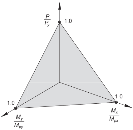
Figure description:
| Axis / Variable | Normalized Ratio | Intercept Value |
|---|---|---|
| Axial Load | 1.0 | |
| Bending Moment (x-axis) | 1.0 | |
| Bending Moment (y-axis) | 1.0 |
Fig. C-E3.1. Linear yield surface for biaxial bending.
where
- axial yield strength of wide-flange section, kips (N)
Equation C-E3-4 can be reconfigured to provide the plastic moment about the strong axis (taken as the x-axis) while including the flexural demand about the weak axis (taken as the y-axis). The strong-axis plastic moment for a wide-flange shape can be taken as Equation C-E3-5:
(C-E3-5)
Similarly, the weak-axis plastic moment for a wide-flange shape can be taken as Equation C-E3-6. This equation is provided for illustration only because beam-to-column connections are not yet prequalified for framing into the weak axis of a wide-flange column.
(C-E3-6)
More accurate estimates for a wide-flange section may be obtained using a nonlinear interaction equation, like Equation C-E3-7, based on Tebedge and Chen (1974):
(C-E3-7)
where and can be determined from Equations C-E3-2 and C-E3-3, respectively. The exponent for a wide-flange section is given by Equation C-E3-8:
(C-E3-8)
It is common in the case of a cruciform-type column built up from orthogonal flanged sections that each axis is treated independently of the other, neglecting the perpendicular section properties, and Equation E3-2 is applicable for each axis. This decoupled approach is appropriate where the only attachment between the orthogonal sections occurs at the neutral axis of each section such that flexural actions in one section do not significantly influence the state of stress in the orthogonal section. Where built-up sections are substantially attached at locations other than the neutral axis of each section—for example at the toes of flanges in cruciform-type columns built up from orthogonal flanged sections—the biaxial bending of the built-up column shape should be considered.
E3.4 System Requirements
E3.4a Moment Ratio
As noted, the strong-column/weak-beam (SC/WB) concept is often mistakenly assumed to be formulated to prevent any column flange yielding in a frame and that if such yielding occurs, the column will fail. Tests have shown that yielding of columns in moment frame subassemblages does not necessarily reduce the lateral strength at the expected seismic displacement levels.
The SC/WB concept is more of a global frame concern than a concern at the interconnections of individual beams and columns. Schneider et al. (1991) and Roeder (1987) showed that the real benefit of meeting SC/WB requirements is that the columns are generally strong enough to force flexural yielding in beams in multiple levels of the frame, thereby achieving a higher level of energy dissipation in the system. Weak column frames, particularly those with weak or soft stories, are likely to exhibit an undesirable response at those stories with the highest column demand-to-capacity ratios.
Compliance with the SC/WB concept and Equation E3-1 gives no assurance that individual columns will not yield, even when all connection locations in the frame comply. Nonlinear response history analyses have shown that, as the frame deforms inelastically, points of inflection shift and the distribution of moments varies from the idealized condition. Nonetheless, yielding of the beams rather than the columns will predominate, and the desired inelastic performance will, in general, be achieved in frames with members sized to meet the requirement in Equation E3-1.
Early formulations of the SC/WB relationship idealized the beam/column intersection as a point at the intersection of the member centerlines. Post-Northridge beam-to-column moment connections are generally configured to shift the plastic hinge location into the beam away from the column face, and a more general formulation was needed. ANSI/AISC 358 provides procedures to calculate the location of plastic hinges for the connections included therein. For other configurations, the locations can be determined from the applicable qualifying tests. Recognition of expected beam strength (see Commentary Section A3.2) is also incorporated into Equation E3-1.
Three exceptions to Equation E3-1 are given. In the first exception, columns with low axial loads used in one-story buildings or in the top story of a multistory building need not meet Equation E3-1 because concerns for inelastic soft or weak stories are not significant in such cases. Additionally, exception is made for columns with low axial loads, under certain conditions, to provide design flexibility where the requirement in Equation E3-1 would be impractical, such as at large transfer girders. Finally, an exception is provided for columns in levels that are significantly stronger than in the level above because column yielding at the stronger level would be unlikely.
As part of the exception, it is necessary to calculate the available shear strength of the exempted moment frame columns and the nonexempted moment frame columns. There are several approaches that may be used to calculate these quantities. The User Note in Section E3.4a provides guidance on two options, and these options along with a third are as follows:
- (1) The User Note states that the available shear strengths of the columns can be calculated considering the flexure at each end of the column as limited by the flexural strength of the attached beams. Columns that satisfy the SC/WB requirement [see Figures C-E3.2(b) and C-E3.2(c)] would have a shear strength, , equal to the following:
where
- = projection of the nominal flexural strength of the beam to the centerline of the column as calculated according to Section E3.4a, kip-in. (N-mm). The calculation is made for each beam, , rigidly framing into the joint. To be consistent with the way the column flexural strength is calculated, the beam nominal flexural strength should be used, neglecting the factor. Similar to the SC/WB check, the moment capacities of all beams framing into the joint (either one or two) are summed.
Columns that don't satisfy the SC/WB requirement [see Figures C-E3.2(d) and C-E3.2(e)] would have a shear strength, , equal to the following:
where
= projection of the nominal flexural strength of the column to the centerline of the beam as calculated according to Section E3.4a, kip-in. (N-mm). The calculation is made for each column, , which includes two columns if the column extends above the joint, and one column otherwise.
Projecting the nominal flexural strength of the beam, , from face of column to centerline of column, or the nominal flexural strength of the column, , from face of beam to centerline of beam, can be done by multiplying the moments by and , respectively. The lengths and heights are shown in Figure C-E3.2(a) as the distance between beam plastic hinges, , the distance between column centerlines, , the distance between beam centerlines, , and the clear height between beams, .
- (2) The User Note also states that the available shear strengths of the columns can alternatively be calculated based on the flexural strength of the columns. This is similar to Equation C-E3-10 for columns not satisfying SC/WB requirements, but in this case, it is applied to all columns. Compared to the first option, this method increases the shear strength for the nonexempt columns, thus making the contribution of exempt columns to story shear strength seem smaller than it is. The first option provides a more accurate assessment of story shear strength than this method.
- (3) A nonlinear pushover analysis could also be conducted on the individual story to calculate available shear strength of the story and the contribution of the exempt columns to the available shear strength. A vertical distribution of lateral loads consistent with ASCE/SEI 7 and proportionally scaled up could be used, and the available shear strength for a column or group of columns could be
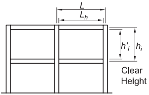
Figure description:
Key Information:
- Structure: A two-story, two-bay structural frame.
- Variables:
- : Center-to-center distance between columns.
- : Clear horizontal distance between column faces.
- : Floor-to-floor or story height.
- : Clear vertical height (Clear Height between beams.
(a) Definition of some variables
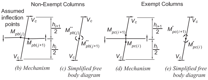
Figure description:
The image shows structural engineering diagrams for calculating column shear ( based on assumed inflection points at mid-height (.
Non-Exempt Columns
- (b Mechanism: Shows a beam-to-column joint with plastic hinges forming in the beams ( and .
- (c Simplified free body diagram: Represents the moments as internal couples ( and acting on the column to determine shear .
Exempt Columns
- (d Mechanism: Shows plastic hinges forming in the columns above and below the joint ( and .
- (e Simplified free body diagram: Represents the column plastic moments ( and as couples used to calculate column shear .
Key Variables
- : Column shear force.
- : Heights of column segments.
- : Plastic moment capacities of beams and columns, respectively.
Fig. C-E3.2. Diagram showing calculation of column shear for the first option.
calculated as the difference in column shear above and below the floor level in question.
A design example demonstrating how to address this issue is included in the AISC Seismic Design Manual (AISC, 2018).
In applying Equation E3-1, recognition should be given to the location of column splices above the beam-to-column connection being checked. When the column splice is located at 4 ft (1.2 m) or more above the top of the girder, it has been customary to base the calculation on the column size that occurs at the joint. If the column splice occurs closer to the top of the beam, or when the column above the splice is much smaller than that at the joint, consideration should be given to whether the column at the joint is capable of providing the strength assumed using the customary approach.
E3.4b Stability Bracing of Beams
See Commentary Section D1.2b on stability bracing of highly ductile members.
In addition to bracing along the beam length, the provisions of Section D1.2c call for the placement of lateral bracing near the location of expected plastic hinges. Such guidance dates to the original development of plastic design procedures in the early 1960s. In moment frame structures, many connection details attempt to move the plastic hinge a short distance away from the beam-to-column connection. Testing carried out as part of the SAC program (FEMA, 2000a) indicated that the bracing provided by typical composite floor slabs is adequate to avoid excessive strength deterioration up to the required story drift angle of 0.04 rad. Therefore, the FEMA recommendations do not require the placement of supplemental lateral bracing at plastic hinge locations adjacent to column connections for beams with composite floor construction. These Provisions allow the placement of lateral braces to be consistent with the tested connections that are used to justify the design. If a reduced beam section connection detail is used, the reduced flange width may be considered in calculation of the bracing force. The requirements pertaining to protected zones given in Section E3.5c should be considered when placing bracing connections.
E3.4c Stability Bracing at Beam-to-Column Connections
Columns of SMF are required to be braced to prevent rotation out of the plane of the moment frame because of the anticipated inelastic behavior in, or adjacent to, the beam-to-column connection during high seismic activity.
E3.4c.1 Braced Connections
Beam-to-column connections are usually braced laterally by the floor or roof framing. When this is the case and it can be shown that the column remains elastic outside of the panel zone, lateral bracing of the column flanges is required only at the level of the top flanges of the beams. If it cannot be shown that the column remains elastic, lateral bracing is required at both the top and bottom beam flanges because of the potential for flexural yielding and consequent lateral-torsional buckling of the column.
The required strength for lateral bracing at the beam-to-column connection is 2% of the nominal strength of the beam flange. In addition, the element(s) providing lateral bracing should provide adequate stiffness to inhibit lateral movement of the column flanges (Bansal, 1971). In some cases, a bracing member will be required for such lateral bracing (direct stability bracing). Alternatively, calculations may show that adequate lateral bracing can be provided by the column web and continuity plates or by the flanges of perpendicular beams (indirect stability bracing).
The 1997 Provisions (AISC, 1997b) required column lateral bracing when the ratio in Equation E3-1 was less than 1.25. The intent of this provision was to require bracing to prevent lateral-torsional buckling for cases where it cannot be assured that the column will not hinge. Studies utilizing inelastic analyses (Gupta and Krawinkler, 1999; Bondy, 1996) have shown that, in severe earthquakes, plastic hinging can occur in the columns even when this ratio is significantly larger than 1.25. (See also discussion under Commentary Section E3.4a.) The revised limit of was selected as a reasonable cutoff because column plastic hinging for values greater than only occurs in the case of extremely large story drifts. The intent is to encourage appropriate bracing of column flanges rather than to force the use of much heavier columns, although other benefits may accrue by use of heavier columns, including possible elimination of continuity and doubler plates that may offset the additional material cost.
E3.4c.2 Unbraced Connections
Unbraced connections occur in special cases, such as in two-story frames, at mechanical floors, or in atriums and similar architectural spaces (multi-tier conditions). When such connections occur, the potential for out-of-plane buckling at the connection should be minimized. Three provisions are given for the columns to limit the likelihood of column buckling.
E3.5 Members
E3.5a Basic Requirements
Reliable inelastic deformation capacity for highly ductile members requires that width-to-thickness ratios of projecting elements be limited to cross sections resistant to local buckling well into the inelastic range. Although the width-to-thickness ratios for compact elements in Specification Table B4.1 are sufficient to prevent local buckling before the onset of yielding, available test data suggest that these limits are not adequate for the required inelastic rotations in SMF. The limits given in Table D1.1 are deemed adequate for the large ductility demands to which these members may be subjected (Sawyer, 1961; Lay, 1965; Kemp, 1986; Bansal, 1971).
E3.5b Beam Flanges
Abrupt changes in beam flange area in locations of high strain, as occurs in plastic hinge regions of SMF, can lead to fracture due to stress concentrations. For connections such as the reduced beam section (RBS), the gradual flange area reduction, when properly configured and fabricated, can be beneficial to the beam and connection performance. Such conditions are permitted when properly substantiated by testing.
E3.5c Protected Zones
For commentary on protected zones, see Commentary Section D1.3.
E3.6 Connections
E3.6a Demand Critical Welds
For general commentary on demand critical welds, see Commentary Section A3.4.
The requirement to use demand critical welds for complete-joint-penetration (CJP) groove welded joints in beam-to-column connections of SMF was first included in the 2002 Provisions (AISC, 2002). The requirement for notch-tough welds with Charpy V-notch toughness of 20 ft-lbf (27 J) at was introduced in the 1999 Supplement No. 1 to the 1997 Provisions. FEMA 350 (FEMA, 2000a) and 353 (FEMA, 2000b) recommended that supplemental requirements beyond this basic toughness should be applied to CJP welds in these connections. Welds for which these special requirements apply are referred to as demand critical welds.
The requirement to use demand critical welds for groove welded column splices and for welds at column base plates was new to these Provisions in 2010 (AISC, 2010b). The change was made because, although it is likely that, in general, strain demands at near-mid-height column splice locations are less severe than those at beam-to-column joints, Shen et al. (2010) showed that bending at these locations can be large enough to cause flange yielding. This fact, coupled with the severe consequence of failure, was the justification for this requirement.
For the case of column-to-base plate connections at which plastic hinging is expected in the column, the condition is very similar to the condition at a beam-to-column connection. Where columns extend into a basement or are otherwise restrained in such a way that the column hinging will occur at a level significantly above the base plate, this requirement is judged to be overly conservative, and an exception is provided.
E3.6b Beam-to-Column Connections
This section gives the performance and design requirements for the connections, with a special provision that outlines requirements for the use of PR connections when justified by analysis; see Commentary Section E3.2. Section E3.6c provides the requirements for verifying that the selected connections will meet the performance requirements. These requirements have been derived from the research of the SAC Joint Venture as summarized in FEMA 350 (FEMA, 2000a).
FEMA 350 recommends two criteria for the qualifying drift angle (QDA) for SMF. The “strength degradation” drift angle, as defined in FEMA 350, means the angle where “either failure of the connection occurs, or the strength of the connection degrades to less than the nominal plastic capacity, whichever is less.” The “ultimate”
drift angle capacity is defined as the angle “at which connection damage is so severe that continued ability to remain stable under gravity loading is uncertain.” Testing to this level can be hazardous to laboratory equipment and staff, which is part of the reason that it is seldom done. The strength degradation QDA is set at 0.04 rad, and the ultimate QDA is set at 0.06 rad. These values formed the basis for extensive probabilistic evaluations of the performance capability of various structural systems (FEMA, 2000d) demonstrating with high statistical confidence that frames with these types of connections can meet the intended performance goals. For the sake of simplicity, and because many connections have not been tested to the ultimate QDA, the Provisions adopt the single criterion of the strength degradation QDA. In addition, the ultimate QDA is more appropriately used for the design of high-performance structures.
Although connection qualification primarily focuses on the level of plastic rotation achieved, the tendency for connections to experience strength degradation with increased deformation is also of concern. Strength degradation can increase rotation demands from effects and the likelihood of frame instability. In the absence of additional information, it is recommended that this degradation should not reduce flexural strength, measured at a drift angle of 0.04 rad, to less than of the plastic moment, , calculated using the specified minimum yield stress, . Figure C-E3.3 illustrates this behavior. Note that 0.03 rad plastic rotation is equivalent to 0.04 rad drift angle for frames with an elastic drift of 0.01 rad.
Commentary Section E2.6b lists the connections that have been prequalified for use in SMF systems as described in ANSI/AISC 358.
The following explains the use of the ANSI/AISC 358 Simpson Strong-Tie® Strong Frame® moment connection, but the discussion may also be applicable to other PR or partial-strength connections that may be added in the future or may be proposed for specific projects.
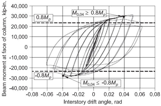
Figure description:
Beam moment at face of column vs. Interstory drift angle
Hysteresis Loop: Beam Moment vs. Interstory Drift
Annotations
- 0.8Mp (horizontal_line - position: y = 23500)
- -0.8Mp (horizontal_line - position: y = -23500)
- M0.04 ≥ 0.8Mp (text_label - position: x = 0.04, y = 29500)
- M0.04 ≤ -0.8Mp (text_label - position: x = -0.04, y = -27500)
| Interstory drift angle, rad | Beam moment at face of column, kip-in. |
|---|---|
| -0.060 | -16000 |
| -0.050 | -23000 |
| -0.040 | -27500 |
| -0.030 | -26500 |
| -0.020 | -24000 |
| -0.010 | -18000 |
| 0.000 | 0 |
| 0.010 | 18000 |
| 0.020 | 25000 |
| 0.030 | 28000 |
| 0.040 | 29500 |
| 0.050 | 30500 |
| 0.060 | 20000 |
Notes: The chart displays the hysteretic response of a beam-column connection. The dashed horizontal lines represent 80% of the plastic moment capacity (0.8Mp. Specific data points at ±0.04 rad drift are highlighted to show they meet the required moment capacity thresholds.)
Fig. C-E3.3. Acceptable strength degradation, per Section E3.6b.
The limitation of was originally adopted based on judgment, before the tools to perform sophisticated nonlinear dynamic analysis were readily available and before the building code, or ASCE/SEI 7, had adopted quantitative performance criteria. The general intent of the building code was that under “severe” but undefined earthquakes, buildings should not collapse. Typical hysteretic curves for highly ductile elements like moment frames (assuming they actually behaved in a ductile manner) were perceived to have the general shape shown in Figure C-E3.4, in which the hysteretic backbone would include an “elastic range,” a “plastic-strain hardening range,” and a “plastic strength-degrading range.”
Based on linear dynamic analysis, typically of idealized single degree of freedom systems, researchers had determined that response of structures with lateral systems that have been pushed into the “strength-degrading” range can be unbounded and lead to collapse or very large lateral displacement. The 80% limitation was implemented to provide some assurance that structures would not be pushed “too far” into the strength degrading range, though the definition of “too far” was not quantified.
Recent tests by Simpson Strong-Tie® have demonstrated yield links in PR connections that were able to develop only about 50% of the beam’s theoretical . Regardless, at 0.04 rad, the connections clearly were not yet reaching the strength-degrading regime of response that the was intended to guard against. Because every connection technology may have quite different hysteretic characteristics, it is not practicable to be able to directly broaden the definition to address all technologies that may be appropriate and that may come forward. Consequently, the requirement has been broadened to allow for the demonstration of equivalent performance through substantiating analysis as an alternate to meeting the threshold.
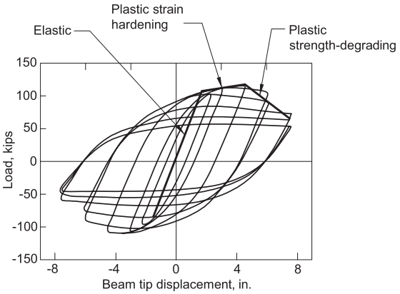
Figure description:
Beam Load-Displacement Response Hysteretic behavior showing elastic, strain hardening, and strength-degrading regions
Load vs. Beam Tip Displacement
Annotations
- Elastic (text_label - position: x ≈ 0.6, y ≈ 40)
- Plastic strain hardening (text_label - position: x ≈ 2.8, y ≈ 112)
- Plastic strength-degrading (text_label - position: x ≈ 5.8, y ≈ 100)
| Beam tip displacement (in.) | Load (kips) | Note |
|---|---|---|
| -7.6 | -45 | End of negative envelope |
| -7.2 | -90 | Outer negative loop |
| -6.0 | -105 | Outer negative loop |
| -4.8 | -112 | Negative peak load |
| -3.5 | -105 | Outer negative loop |
| -2.0 | -80 | Outer negative loop |
| 0.0 | 0 | Origin |
| 0.8 | 55 | Elastic limit |
| 1.8 | 102 | End of elastic / Start hardening |
| 3.0 | 112 | Plastic strain hardening region |
| 4.6 | 118 | Positive peak load |
| 6.0 | 105 | Plastic strength-degrading region |
| 7.6 | 68 | End of positive envelope |
| -1.5 | 45 | Inner cycle turning point |
| 1.5 | -45 | Inner cycle turning point |
| -4.0 | 60 | Inner cycle turning point |
| 4.0 | -60 | Inner cycle turning point |
Notes: The chart illustrates a hysteretic response characteristic of structural elements under cyclic loading. It highlights three distinct mechanical phases: initial elastic behavior, plastic strain hardening until peak capacity, and subsequent strength degradation at higher displacement levels.
Fig. C-E3.4. Load and tip displacement data for a PR-connected cantilevered beam.
In the time since the was adopted as a standard, the industry's ability to perform nonlinear analysis and also the building code's definition of acceptable performance has evolved substantially. The 2010 ASCE/SEI 7 standard (ASCE, 2010) defined acceptable performance in terms of a limiting permissible conditional probability of collapse, given the occurrence of maximum considered earthquake shaking. These definitions are carried forward in the 2022 ASCE/SEI 7 standard (ASCE, 2022). Two documents developed by the Applied Technology Council (ATC) on behalf of FEMA define procedures for assuring that structures meet these performance (noncollapse) criteria; one of these is FEMA P-695 (FEMA, 2009b). FEMA P-695 uses an extension of the probabilistic framework developed by the FEMA/SAC project to qualify post-Northridge moment frames by computing the probability of collapse of frames of given configuration and hysteretic characteristics. The companion document, FEMA P-795 (FEMA, 2011), provides a means of judging whether the substitution of a component-that is, a connection-into a system that has been demonstrated by FEMA P-695 to have adequate collapse resistance will affect that resistance. ASCE/SEI 7, Section 12.2.1, adopts both methodologies as a means of demonstrating acceptable performance either for new structural systems in Section 12.2.1.1 or for substitute components in existing systems in Section 12.2.1.2.
With regard to rotation data for the Simpson Strong-Tie® Strong Frame® connection, ANSI/AISC 358 contains a detailed design procedure for this connection that includes determination of the rotational stiffness of the connection. The procedure requires that this flexibility be considered in determining frame adequacy (drift). The Connection Prequalification Review Panel (CPRP) performed review of available hysteretic test data that substantiates that the connection stiffness representation contained in the design procedure is a reasonable approximation of that obtained in testing.
E3.6c Conformance Demonstration
This section provides requirements for demonstrating conformance with the requirements of Section E3.6b. This section specifically permits the use of prequalified connections meeting the requirements of ANSI/AISC 358 to facilitate and standardize connection design. Connections approved by other prequalification panels may be acceptable but are subject to the approval of the authority having jurisdiction. Use of connections qualified by prior tests or project-specific tests may also be used, although the engineer of record is responsible for substantiating the connection performance. Published testing, such as that conducted as part of the SAC project and reported in FEMA 350 and 355 or project-specific testing, may be used to satisfy this provision.
E3.6d Required Shear Strength
The seismic component of the required shear strength of the beam-to-column connection is defined as the shear that results from formation of the maximum probable moment at the plastic hinge locations, based on the capacity-limited horizontal seismic load effect given by Equation E3-5. This shear must be combined with other shear forces, such as gravity forces, using the load combinations of the applicable building code.
E3.6e Panel Zone
E3.6e.1 Required Shear Strength
Cyclic testing has demonstrated that significant ductility can be obtained through shear yielding in column panel zones through many cycles of inelastic loading (Popov et al., 1996; Slutter, 1981; Becker, 1971; Fielding and Huang, 1971; Krawinkler, 1978; Lee et al., 2005a, 2005b; Shin and Engelhardt, 2013). Consequently, it is not generally necessary to provide a panel zone that will remain elastic under earthquake loading. Initial significant yielding of the panel zone will occur when the shear force in the panel zone reaches the values given by Specification Equations J10-9 and J10-10. However, both experimental and computational studies have shown that panel zones can resist substantially higher shear forces due to strain hardening and due to contributions of the column flanges in resisting panel-zone shear. This additional shear strength is considered in Specification Equations J10-11 and J10-12, which provide an estimate of the shear resistance of the panel zone after moderate levels of cyclic inelastic deformation has occurred. These equations are based on the work by Krawinkler (1978). Skiadopoulos and Lignos (2021) compiled an experimental database of moment-connection tests of inelastic panel-zone behavior. This work indicates somewhat lower strength than Specification Equations J10-11 and J10-12 and provides a more realistic representation of nonlinear behavior.
Despite the ductility demonstrated by properly proportioned panel zones in previous studies, there are concerns that excessive inelastic panel-zone distortions can adversely affect the performance of beam-to-column connections (Krawinkler, 1978; Englekirk, 1999; El-Tawil et al., 1999). Krawinkler noted that large shear distortions of the panel zone result in the formation of localized “kinks” at the corners of the panel zone that can lead to the occurrence of fracture in the vicinity of the beam flange-to-column flange groove welds. Many tests, however, have shown that cyclic joint rotations well in excess of can be achieved prior to the occurrence of fracture (Krawinkler, 1978; Engelhardt et al., 2000; Lee et al., 2005b; Shin and Engelhardt, 2013). In addition to concerns about how shear distortion may affect joint performance, there are also uncertainties on how overall frame performance will be affected when panel zones are substantially weaker than the beams.
To summarize, past research has shown that shear yielding in the panel zone can provide high levels of stable cyclic inelastic deformation and can be an excellent source of ductility in steel moment-resisting frames. However, past research has also suggested that caution is needed in panel-zone design as excessive panel-zone yielding may have adverse effects on joint performance and on overall frame performance. Based on these observations, these Provisions have taken the approach that beam flexural yielding should still be the primary source of inelastic deformation in SMF, but that limited yielding of panel zones is acceptable.
The required strength of the panel zone is defined as the shear force in the panel zone when the fully yielded and strain-hardened flexural strength of the attached beams has been developed. For connections where the beam flanges are welded directly to column flanges, such as the prequalified reduced beam section and welded unreinforced flange-welded web connections in ANSI/AISC 358, the LRFD required shear strength of the panel zone, , can be estimated as follows:
(C-E3-11)
In this equation, is the sum of the beam moments at the face of the column when the beams have achieved their maximum probable moment at the plastic hinge, , as defined in ANSI/AISC 358. is the shear force in the portion of the column outside of the panel zone that occurs when the beams have achieved their maximum probable moment.
The available strength of the panel zone is computed using Specification Section J10.6. As specified in these Provisions, the available strength is computed using (LRFD) or (ASD), reflecting the view that limited panelzone yielding is acceptable.
Specification Section J10.6 provides two options for computing panel-zone available strength. According to the Specification, the first option, given by Specification Equations J10-9 and J10-10, is used “when the effect of inelastic panel-zone deformation on frame stability is not accounted for in the analysis.” The second option, given by Specification Equations J10-11 and J10-12, is used “when the effect of inelastic panel-zone deformation on frame stability is accounted for in the analysis.” As discussed, Specification Equations J10-9 and J10-10 correspond to first significant yield of the panel zone, and using these equations will result in panel zones that remain nominally elastic during earthquake loading. In contrast, Specification Equations J10-11 and J10-12 provide an estimate of the shear resistance after the panel zone has developed moderate inelastic deformation. Design using these equations will result in panel zones that may experience limited inelastic deformation under earthquake loading. Designs meeting code-specified seismic drift limits satisfy the requirements to permit use of Specification Equation J10-11 or J10-12 in conjunction with the required strength from Equation C-E3-11. Drift analysis is required to consider panel-zone flexibility, which is typically addressed by using analyses based on centerline dimensions of the beams and columns, as well as effects. For further discussion on this issue, refer to Hamburger et al. (2009).
These Provisions also permit panel-zone design to be based on tested connections. Considerable caution is needed with this approach if it leads to a panel zone that is significantly weaker than would otherwise be obtained using these Provisions. As described previously, weaker panel zones can increase the propensity for fracture at the beam-to-column connection and can also potentially adversely affect overall frame performance. These potential adverse effects should be carefully evaluated when considering the use of weaker panel zones based on tested connections.
E3.6e.2 Panel-Zone Thickness
Section E3.6e.3 requires a minimum doubler thickness of ¼ in. (6 mm) to prevent use of very thin doubler plates that may result in fabrication and welding difficulties or that may be too weak and/or flexible to adequately brace continuity plates. In addition, Equation E3-6 is required to minimize shear buckling of the panel zone during inelastic deformations. Thus, when the column web and web doubler plate(s) each meet the requirements of Equation E3-6, interconnection with plug welds is not required. Otherwise, the column web and web doubler plate(s) can be interconnected with plug welds as illustrated in Figure C-E3.5, and the total panel-zone thickness can be used in Equation E3-6.
When plug welds are required, Section E3.6e.2 requires a minimum of four plug welds. As a minimum, the spacing should divide the plate into rectangular panels in such a way that all panels meet the requirements of Equation E3-6. Additionally, because a single plug weld would seem to create a boundary condition that is much different than a continuously restrained edge, it would be advisable to place the plug welds in pairs or lines, dividing the plate into
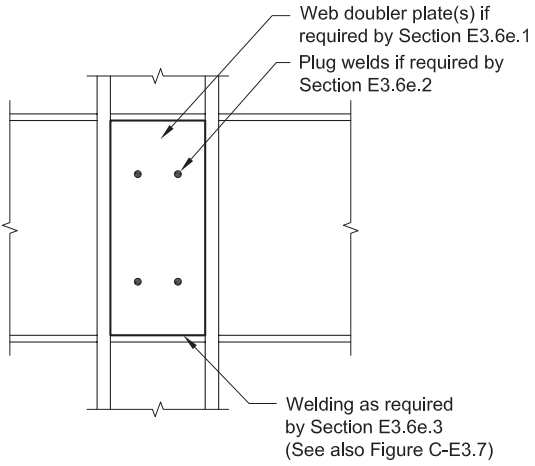
Figure description:
- Figure Type: Structural engineering diagram (Fig. C-E3.5
- Key Entities:
- Web doubler plate(s: Rectangular plate attached to the column web (Section E3.6e.1.
- Plug welds: Four circular welds arranged in a rectangular pattern on the doubler plate (Section E3.6e.2.
- Peripheral welding: Welds around the boundary of the doubler plate (Section E3.6e.3.
- Structural components: Depicts a beam-to-column intersection.
- Key Information: Illustrates the method of connecting web doubler plates using a combination of peripheral welds and internal plug welds to meet specific code requirements.
Fig. C-E3.5. Connecting web doubler plates with plug welds.
approximately equal-sized rectangles. Plug welds, when used, should, as a minimum, meet the requirements of Specification Section J2.3.
An alternative detail is shown in Figure C-E3.6, where web doubler plates are placed symmetrically in pairs spaced away from the column web. In this configuration, both the web doubler plates and the column web are required to each independently meet Equation E3-6 in order to be considered as effective.
E3.6e.3 Panel-Zone Doubler Plates
Requirements for attachment of doubler plates to columns were updated for the 2016 edition of the Provisions based on recent research (Shirsat, 2011; Donkada, 2012; Gupta, 2013) as well as a reevaluation of past research (Mays, 2000; Lee et al., 2005a, 2005b). There are several different conditions using web doubler plates depending on the need for continuity plates and on the particular design conditions. Doubler plates may be placed against the column web or spaced away from the web, and they may be used with or without continuity plates.
Figure C-E3.7 shows doubler plates in contact with the web of the column. The research studies noted previously have shown that force is transferred to the doubler primarily through the welds connecting the vertical edges of the doubler to the column flanges. Two options are available for this weld: a groove weld as shown in Figure C-E3.7(a) or a fillet weld as shown in Figure C-E3.7(b). When a groove weld is used, past versions of these Provisions required CJP groove welds. This was problematic, as there was no prequalified CJP groove weld joint detail in AWS D1.1/D1.1M (AWS, 2020) or earlier versions of AWS D1.8/ D1.8M for this type of joint. Therefore, the Provisions now refer to AWS D1.8/ D1.8M (AWS, 2021), clause 4.3, which includes a prequalified doubler plate-to-column flange joint detail. Further, these Provisions now designate this weld as a PJP groove weld that extends from the surface of the doubler to the column flange [as shown in Figure C-E3.7(a)] and in accordance with the detail in AWS D1.8/D1.8M. Based on a review of all available research, a judgment was made
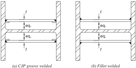
Figure description:
Key Information: Doubler Plate Welding Details
- Entities: Column (with flanges and web, Doubler plates (thickness t.
- Configuration: Doubler plates are spaced equally ("eq." away from the central column web.
- Weld Options:
- (a CJP groove welded: Shows a groove weld joint between the edge of the doubler plate and the column flange, featuring a backing bar or specific joint preparation.
- (b Fillet welded: Shows a fillet weld connecting the outer edge of the doubler plate to the column flange.
Fig. C-E3.6. Doubler plates spaced away from the web.
that routine ultrasonic testing of this weld is not justified. Consequently, the weld is now designated as a PJP groove weld to reflect this view.
When a groove weld is used as shown in Figure C-E3.7(a), an additional concern is welding to the -area of the column web. Welding into the flange/web fillet region, as shown in Figure C-E3.7(a), does not constitute welding in the -area, although it clearly is very close to the -area. To minimize the chances of welding to the -area, it may be helpful to allow the doubler plate edge to land slightly within the flange/web fillet of the column. The Provisions permit a in. ( 2 mm ) gap between the doubler and the column web, as shown in Figure C-E3.7(a), and allow the doubler to still be treated as being in contact with the web when landing within the flange/web fillet. In some cases, welding into the -area (i.e., welding on the flat portion of the column web) may be unavoidable, for example, because of variations in the actual as-rolled dimension of the column.
Figure C-E3.7(b) shows the option of using a fillet weld to connect the vertical edge of the doubler to the column flange. Research (Shirsat, 2011; Donkada, 2012; Gupta, 2013) has shown that the state of stress at the edge of the doubler plate is dominated by vertical shear but that significant horizontal normal stresses are also developed near the top and bottom of the doubler plate in the region of the beam flanges. Consequently, the fillet weld along the vertical edge of the doubler plate is subjected to both vertical shear forces and normal forces perpendicular to the axis of the weld. Although the weld sees both shear and tension, the Provisions state that the required strength of the fillet weld is equal
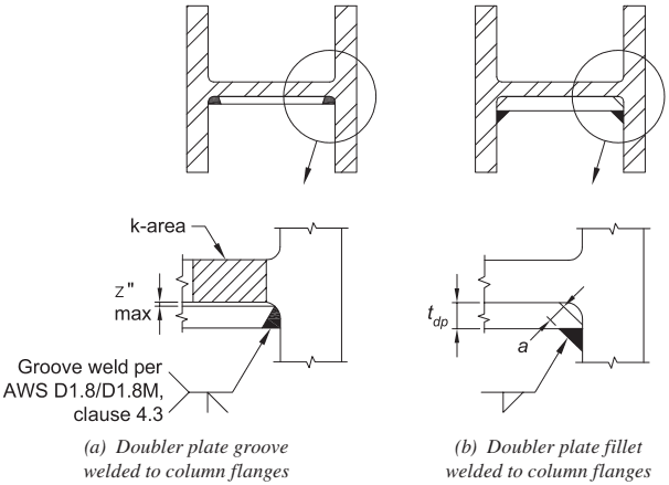
Figure description:
- Figure C-E3.7: Illustrates doubler plate connections to column webs and flanges.
- Section (a: Doubler plate groove welded to column flanges
- Features a groove weld specified per AWS D1.8/D1.8M, clause 4.3.
- Highlights the "k-area" of the column.
- Indicates a maximum gap dimension labeled "z".
- Section (b: Doubler plate fillet welded to column flanges
- Shows the use of fillet welds on both sides of the doubler plate edge.
- Labels the doubler plate thickness as .
- Specifies weld size with dimension "a".
- Key Entities: Column flange, column web, doubler plate, groove weld, fillet weld, k-area.
Fig. C-E3.7. Doubler plate in contact with column web.
to the available shear yielding strength of the full doubler plate thickness, where the available shear yielding strength is computed using Specification Equation J4-3. Sizing the fillet weld for shear will result in adequate strength for the weld loaded in tension because the available strength of fillet welds loaded perpendicular to the weld's longitudinal axis is 50% higher than the available strength of a fillet weld loaded in shear along its longitudinal axis. For a doubler plate with a specified minimum yield stress of 50 ksi (345 MPa) and a weld filler metal with , a fillet weld with a leg size of 1.35 times the doubler plate thickness will develop the available shear yielding strength of the doubler plate. This same fillet weld size will also be adequate to develop the available tension yielding strength of the doubler plate. Thus, by sizing the fillet weld to develop the available shear strength of the doubler plate, the weld inherently has sufficient capacity to develop the available strength in pure tension or in a combined tension/shear stress state.
Using a fillet weld to connect the vertical edge of a doubler plate to the column flange when the doubler plate is in contact with the column web will normally require a bevel at the edge of the doubler plate to clear the column flange/web fillet as shown in Figure C-E3.7(b). When such a bevel is used, the shear strength of the doubler plate may be controlled by the section defined by the minimum distance from the toe of the fillet weld to the edge of the doubler along the bevel. This minimum distance is shown by the dimension in Figure C-E3.7(b). When the dimension, , is less than the full doubler plate thickness, , then the shear yielding strength of the full doubler plate thickness cannot be developed. Consequently, the size of the fillet weld and the geometry of the bevel should be proportioned so that . This may require increasing the size of the fillet weld beyond that needed to satisfy weld strength requirements. Note, however, that large fillet welds placed on relatively thin doubler plates can produce considerable welding-induced distortion in the doubler. As an alternative, the thickness of the doubler plate, , can be increased so that shear yielding along the section defined by provides the required panel-zone shear strength.
When a single, thick doubler plate in contact with the column web is welded to the column flanges, considerable welding-induced distortion may occur in the column flanges. These welding distortion problems can be somewhat alleviated by splitting the doubler and placing doublers of similar thickness on each side of the web. For example, a 1-in.- (25-mm-) thick doubler plate is needed to provide adequate panel-zone shear strength. This can be accommodated by using a single 1-in.- (25-mm-) thick plate on one side of the column web, or by using ½-in.- (13-mm-) thick doubler plates on both sides of the column web. The decision to split a doubler can be made in conjunction with the fabricator or it can be left to the discretion of the fabricator.
As an alternative to placing doubler plates in contact with the web, it is also permissible to use doubler plates spaced away from the web, as shown in Figure C-E3.6. Spaced doubler plates must be provided in symmetric pairs and can be connected to the column flanges using CJP groove welds as shown in Figure
C-E3.6(a), fillet welds as shown in Figure C-E3.6(b), or built-up PJP groove welds. If CJP groove welds are used, removal of backing bars is not required.
When doubler plates are used without continuity plates, they are required to extend a minimum of 6 in. (150 mm) above and below the deepest beam framing into the column, as shown in Figure C-E3.8. This extension permits a more uniform transfer of stress to the doubler and to the doubler-to-column flange weld in the region near the beam flanges. It also places the termination of the doubler-to-column flange weld away from the highly stressed region near the beam flanges. When doubler plates are extended above and below the joint as shown in Figure C-E3.8, research (Shirsat, 2011; Donkada, 2012; Gupta, 2013) has shown that fillet welds are not required along the top and bottom edges of the doubler plate. The only exception is when either the doubler plate or column web thickness does not satisfy Equation E3-6. In this case, minimum size fillet welds are required along the top and bottom edges of the doubler plate to help maintain stability of the panel zone, in addition to the plug welds required in Section E3.6e.2. When fillet welds are provided along the top and bottom edges of the doubler plate, these welds should not extend into the -area of the column.
When doubler plates are used with continuity plates, they may be located between the continuity plates, or they may be extended above and below the continuity plates. Figure C-E3.9(a) shows an example of an extended doubler plate used with continuity plates. This case requires that the continuity plate be welded to the doubler plate. Research examining this case (Donkada, 2012; Gupta, 2013) has shown that welding the continuity plate to the doubler plate does not substantially change the shear force in the doubler plate; that is, the forces and state of stress in the doubler plate are very similar with or without the continuity plate. However, all requirements of the Specification must be satisfied. Specification Section J10.8 assumes a model in which the stiffener transfers the difference in force between the required strength (the flange force) and available strength of the unstiffened column. The doubler plate, by itself, must have sufficient shear strength to resist the difference between the flange force and the available strength of the unstiffened column computed according to Specification Section J10 for the lesser of the limit states of flange local bending, web local yielding, and web local crippling. The required shear strength computed according to the difference in these forces need not be added with the shear force in the doubler plate due to the panel-zone shear force. For some SMF beam-to-column joint configurations, Specification Section J10 may indicate that no continuity plates are required, but Equations E3-7 and E3-8 will still require continuity plates. For these cases, no special consideration is needed in the design of the doubler plate. Recent research has also shown that no welds are needed along the top and bottom edges of an extended doubler plate when continuity plates are present. In cases where the doubler-plate thickness does not satisfy Equation E3-6, the continuity plate serves to help restrain buckling of the doubler plate, and consequently, welds at the top and bottom edges of the doubler plate are not needed.
Figure C-E3.9(b) shows an example of a doubler plate placed between continuity plates. For this case, welding the doubler to the continuity plate is required. This weld should extend over the full width of the continuity plate between -areas of the column and should be designed to develop at least of the shear yielding strength of the doubler over its contact length with the continuity plate. The doubler-to-continuity plate weld helps transfer force to the doubler and reduces stress concentrations near the ends of the doubler-to-column flange welds. For a doubler plate with a specified minimum yield stress of 50 ksi (345 MPa) and a weld filler metal with , the strength requirement for the doubler-to-continuity plate weld can be satisfied by specifying a PJP groove weld with an effective throat equal to the doubler plate thickness. Other options for welding the doubler plate to the continuity plate are provided in AISC Design Guide 13, Stiffening of Wide-Flange Columns at Moment Connections: Wind and Seismic Applications (Carter, 1999). Detailing this weld requires consideration of how the continuity plate-to-column weld will be combined with the doubler-to-continuity plate weld. Detailing and sequencing of these combined welds can be made in conjunction with the fabricator.
The use of diagonal stiffeners for strengthening and stiffening of the panel zone has not been adequately tested for low-cycle reversed loading into the inelastic range; thus, no specific recommendations are made at this time for special seismic requirements for this detail.
E3.6f Continuity Plates
Beam-flange continuity plates serve several purposes in moment connections. They help to distribute beam-flange forces to the column web, they stiffen the column web to prevent local crippling under the concentrated beam flange forces, and they
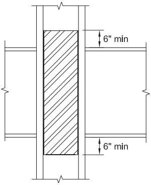
Figure description:
Entities and Details:
- Subject: Doubler plate used without continuity plates in a steel moment connection.
- Column: Vertical steel member with a central web and side flanges.
- Beams: Horizontal steel members connected to both sides of the column.
- Doubler Plate: A cross-hatched rectangular reinforcement plate attached to the column web.
- Minimum Dimensions: The doubler plate extends a minimum of 6 inches above the top beam flange and a minimum of 6 inches below the bottom beam flange.
Fig. C-E3.8. Doubler plates used without continuity plates.
minimize stress concentrations that can occur in the joint between the beam flange and the column due to nonuniform stiffness of the column flange.
E3.6f.1 Conditions Requiring Continuity Plates
Conditions requiring continuity plates are determined based on Specification Section J10. Equations in the User Note are provided for calculation of the required strength at the column face for use in checking the local limit states in the column that are required by Specification Section J10. In addition, Equations E3-7 and E3-8 are intended to provide a lower bound on the stiffness of the column flange based on its thickness in relation to the width of the beam flange. Column flanges not meeting the limits given in these equations will deflect more under the beam flange load, which may lead to undesirable stress patterns at the beam-to-column flange weld. Justification for the use of Equation E3-7 is based on studies discussed in FEMA 355D (FEMA, 2000c). Subsequent research by Lee et al. (2005a) confirmed the adequacy of designs based on these equations.
The design equations for continuity plates have been developed based on consideration of the behavior of columns in lower stories of buildings, where the column extends a considerable distance above the top flange of the connected beam. These equations do not apply in the top story of a building, where the
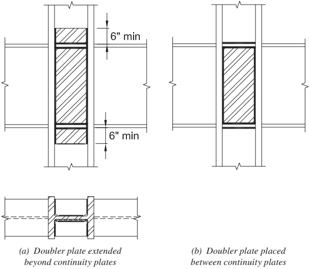
Figure description:
Fig. C-E3.9. Doubler plate used with continuity plates.
- (a Doubler plate extended beyond continuity plates:
- Doubler plate (hatched area extends a minimum of 6 inches above the top and below the bottom continuity plates.
- Cross-section view shows the doubler plate positioned against the column web between the flanges.
- (b Doubler plate placed between continuity plates:
- Doubler plate is contained within the vertical limits of the upper and lower continuity plates.
- Key Components:
- Vertical steel column with horizontal beam connections.
- Horizontal continuity plates.
- Hatched doubler plate for web reinforcement.
Fig. C-E3.9. Doubler plate used with continuity plates.
column terminates at approximately the level of the top flange of the beam. In such cases, beam-flange continuity plates or column cap plates, having a thickness not less than that of the connected beam flange, should be provided. Figure C-E3.10 presents a detail for such a connection, where the beam flange is welded directly to the cap plate and the cap plate is welded to the column so as to deliver the beam-flange forces to the column web.
Alternatively, if the column projects sufficiently above the beam top flange, the preceding methods can be considered valid. Although comprehensive research to establish the necessary distance that the column must extend above the beam for this purpose has not been performed, it may be judged to be sufficient if the column is extended above the top beam flange a distance not less than or , whichever is less, where is the depth of the column and is the width of the column flange.
Requirements for continuity plates in boxed wide-flange columns are not provided. It is recommended that designers perform appropriate analyses, consult research, and/or conduct tests to determine the need for continuity plates for box columns. Analyses to demonstrate that continuity plates are not needed should demonstrate that the nonlinear stress and strain patterns in the beam-to-column flange welds are consistent with those of tested connections.
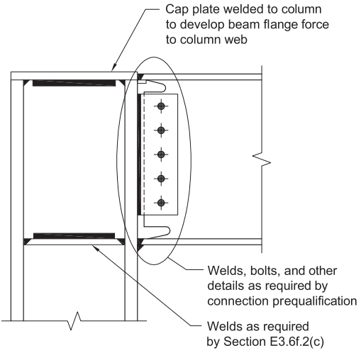
Figure description:
Diagram: Fig. C-E3.10. Cap plate detail at column top
- Cap Plate: Welded to the top of the column to transfer beam flange forces to the column web.
- Beam-to-Column Connection: Includes welds and a bolted shear tab; specific details (welds, bolts are governed by connection prequalification.
- Weld Requirements: Internal or specified welds are noted as required by Section E3.6f.2(c.
- Key Entities: Boxed column, horizontal beam, cap plate, shear plate with five bolts, and various weld points.
Fig. C-E3.10. Cap plate detail at column top.
E3.6f.2 Continuity Plate Requirements
The size and welding requirements of continuity plates in this section are intended for situations specified in Section E2.6f for IMF, Section E3.6f.1 for SMF, and option (c) in Section E1.6b for OMF. Therefore, stringent requirements like using CJP welds to connect continuity plates to column flanges are limited to SMF and IMF applications. When continuity plates are used that are not intended to resist beam flange force due to hinging of the beams, the sizing and welding requirements of the continuity plates should follow the Specification.
Requirements to determine the thickness of continuity plates are based on studies by FEMA 355D (FEMA, 2000c) and Lee et al. (2005a). Continuity plates with these minimum thicknesses have been shown to have adequate stiffness and strength to enable a relatively uniform distribution of strain across the flange of the connecting girder.
Previous versions of the Provisions required a minimum continuity plate thickness for two-sided connections equal to the full thickness of the thicker beam flange, largely based on the use of full-thickness continuity plates in successfully tested connections. Although the references noted indicate that continuity plates of thickness equal to one-half of the thicker beam flange thickness can provide adequate performance for these connections, a more conservative value of three-quarters of the thicker beam flange is used to address the range of demands that may be seen in two-sided connections as compared to one-sided connections.
Buckling of a continuity plate was observed in an AISC-sponsored test program (Reynolds and Uang, 2022). Because previous editions of these Provisions did not provide a requirement for the width-to-thickness ratio for continuity plate design, a limiting width-to-thickness ratio, , is provided in Equation E3-9, which is similar to Case 1 of Specification Table B4.1a and has been verified through finite element simulation and available test data. The only difference is that the nominal yield stress, , in the Specification is replaced by the expected yield stress, , for consistency with the format in Table D1.1.
The connection of continuity plates to column webs is designed to be capable of transmitting the maximum shear forces that can be delivered to the connection. This may be limited by the beam-flange force, the shear strength of the continuity plate itself, the welded joint between continuity plate and column flange, or the strength of the column panel zone.
The Provisions require that continuity plates be attached to column flanges with CJP groove welds or two-sided fillet welds in order that the strength of the beam flange can be properly developed into the continuity plate. Research by Lee et al. (2005a, 2005b) and Reynolds and Uang (2022) have demonstrated that moment connections with a pair of fillet welds to connect the continuity plate to the column flange perform adequately. In particular, the latter AISC-sponsored test program involving cyclic testing of five one-sided reduced beam section connections and four two-sided welded unreinforced flange-welded web connections demonstrated that connections designed with the proposed fillet weld requirement met the requirements of Section E3.6b. For single-sided connections in which a moment-connected beam attaches to only one of the column flanges, it is theoretically not necessary to attach the continuity plate to the column flange that does not have a beam attached because there is no quantifiable force to transfer from the column flange to the continuity plate. In such cases, acceptable performance is expected if the continuity plate is attached to the column with a pair of minimum-size fillet welds.
E3.6g Column Splices
In the 1997 Provisions, there were no special requirements for column splices in SMF systems other than those currently given in Section D2.5. The requirement in Section D2.5a was intended to address column bending at the splice by requiring splices to be at least 4 ft (1.2 m) or one-half the column clear height from the beam-to-column connection. This requirement was based on general recognition that in elastic analyses of moment frames, the columns are typically bent in double curvature with an inflection point somewhere near the middle of the column height, and therefore, little bending of the column was expected at the splice.
Nonlinear analyses performed during the FEMA/SAC project following the Northridge earthquake, and subsequently (Shen et al., 2010; Galasso et al., 2015) clearly demonstrated that bending moments in the mid-height of columns can be substantial and that, in fact, the columns may be bent in single curvature under some conditions. Given this fact, and recognition of the potential for severe damage or even collapse due to failure of column splices, the need for special provisions for splices of moment frame columns was apparent.
The provisions of Section E3.6g are intended to develop a stress of 55 ksi (380 MPa)— for ASTM A992/A992M steel—in the flange of the smaller column, either through use of CJP groove welds or another connection that provides similar strength, and that the shear strength of the splice is sufficient to resist the shear developed when occurs at each end of the spliced column, where is the plastic moment.
The provisions in Section E3.6g.2, permitting the use of PJP groove welds in column splices, is based on testing (Shaw et al., 2015). This testing, along with fracture mechanics simulation (Stillmaker et al., 2015), has demonstrated that if detailed appropriately, splices constructed with PJP groove welds provide strength similar to splices with CJP groove welds and are able to develop a stress of 55 ksi (380 MPa) in the smaller column. Previous editions of these Provisions did not permit PJP welds in splices in SMF and IMF because the unfused weld root in the PJP weld was considered to be a potential initiator of fracture. However, this recent research shows that fracture toughness demands at the weld root are lower than the toughness capacity implied by minimum Charpy V-notch toughness requirements, if the requirements of this section are satisfied. The scientific basis for these requirements is as follows:
- (1) The fracture toughness demand is directly related to the length of the unfused weld root relative to the flange thickness. Requiring the effective throat thickness to be at least 85% of the thinner flange limits the length of the unfused weld root relative to flange thickness.
- (2) The potential fracture plane is at the location of the weld root. Requiring the thicker flange to be 5% thicker than the thinner flange, along with the requirement for the transition reinforcement, limits the fracture toughness demand at the weld root by preserving a sufficient net section in the fracture plane. Similar considerations motivate the detailing requirements for the web.
- (3) The requirement for smooth, tapered transitions is based on ensuring similarity to the specimens tested by Shaw et al. (2015) and the general undesirability of sharp flaws and stress risers in welded connections.
Figure C-E3.11 illustrates details that are compliant with the Provisions. Figure C-E3.11(a) shows a PJP splice detail with a single weld deposited from the outside of the flange. This may be feasible for thinner flanges [thickness less than 2½ in. (63 mm)] and does not require an access hole in the column web. Figure C-E3.11(b) shows a PJP splice detail with a double-sided flange weld, which may be required for thicker flanges.