F3.1 Scope
Eccentrically braced frames (EBF) are composed of columns, beams, and braces. The distinguishing characteristic of an EBF is that at least one end of every brace is connected so that the brace force is transmitted through shear and bending of a short beam segment, called the link, defined by a horizontal eccentricity between the intersection points of the two brace centerlines with the beam centerline or between the intersection points of the brace and column centerlines with the beam centerline for links adjacent to columns. In contrast with concentrically braced frames, beams in EBF are always subjected to high shear and bending forces. Figure C-F3.1 illustrates some examples of EBF and the key components: the links, the beam segments outside of the links, the diagonal braces, and the columns.
These Provisions are primarily intended to cover the design of EBF in which the link is a horizontal framing member located between the column and a brace or between two braces. For the inverted Y-braced EBF configuration shown in Figure C-F3.1(d),
a = link
- b = beam segment outside of link
- c = diagonal brace
- d = column
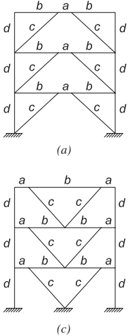
Figure description:
- Two structural diagrams of three-story frames labeled (a and (c.
- Both frames consist of vertical columns labeled d and diagonal braces labeled c.
- Diagram (a: Inverted V-bracing (chevron configuration. Horizontal beams are divided into three segments labeled b, a, and b.
- Diagram (c: V-bracing configuration. Horizontal beams are divided into three segments labeled a, b, and a.
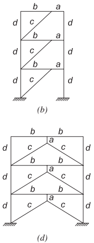
Figure description:
The image illustrates two configurations of eccentrically braced frames (EBFs with components labeled as follows:
- a: Link (the eccentric segment of the beam designed for energy dissipation
- b: Beam segment outside of the link
- c: Diagonal brace
- d: Column
Frame Configurations:
- (b Single Diagonal EBF: A three-story frame where each story has one diagonal brace offset from the beam-column joint, creating a link ('a' at one end of the beam.
- (d Chevron (V-shaped EBF: A three-story frame where braces meet at the center of the beam but are offset from each other, creating a link ('a' in the middle of the span.
Fig. C-F3.1. Examples of eccentrically braced frames.
the link is attached underneath the beam. If this configuration is to be used, lateral bracing should be provided at the intersection of the diagonal braces and the vertical link, unless calculations are provided to justify the design without such bracing.
F3.2 Basis of Design
Research has shown that EBF can provide an elastic stiffness that is comparable to that of SCBF and OCBF, particularly when short link lengths are used, and excellent ductility and energy dissipation capacity in the inelastic range, comparable to that of SMF, provided that the links are not too short (Roeder and Popov, 1978; Libby, 1981; Merovich et al., 1982; Hjelmstad and Popov, 1983; Malley and Popov, 1984; Kasai and Popov, 1986b, 1986c; Ricles and Popov, 1987a, 1987b; Engelhardt and Popov, 1989a, 1989b; Popov et al., 1989). Inelastic action in EBF under seismic loading is restricted primarily to the links. These provisions are intended to ensure that cyclic yielding in the links can occur in a stable manner while the diagonal braces, columns, and portions of the beam outside of the link remain essentially elastic under the forces that can be developed by fully yielded and strain-hardened links.
In some bracing arrangements, such as that illustrated in Figure C-F3.2, with links at each end of the brace, links may not be fully effective. If the upper link has a significantly lower design shear strength than that of the link in the story below, the upper link will deform inelastically and limit the force that can be developed in the brace and transferred to the lower link. When this condition occurs, the upper link is termed an active link and the lower link is termed an inactive link. The presence of potentially inactive links in an EBF increases the difficulty of analysis.
It can be shown with plastic frame analyses that, in some cases, an inactive link will yield under the combined effect of dead, live, and earthquake loads, thereby reducing the frame strength below that expected (Kasai and Popov, 1984). Furthermore, because inactive links are required to be detailed and constructed as if they
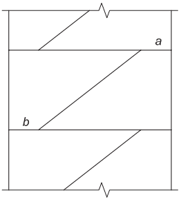
Figure description:
- Entities:
- Vertical Members: Structural columns forming the frame boundaries.
- Horizontal Members: Floor beams connecting the columns.
- Diagonal Braces: Bracing elements intersecting the horizontal beams.
- Link 'a' (Active Link: Segment of the beam between a column and the diagonal brace.
- Link 'b' (Inactive Link: Segment of the beam between a column and the diagonal brace at a different location.
- Key Principle: The nominal shear strength ( of active link 'a' is less than that of inactive link 'b' (.
- Configuration: Eccentrically Braced Frame (EBF showing staggered link placement across multiple floor levels.
of link (active link) of link (inactive link)
Fig. C-F3.2. EBF-active and inactive links.
were active, and because a predictably inactive link could otherwise be designed as a pin, the cost of construction is needlessly increased. Thus, an EBF configuration that ensures that all links will be active, such as those illustrated in Figure C-F3.1, is recommended. Additional recommendations for the design of EBF are available (Popov et al., 1989).
Columns in EBF are designed following capacity design principles so that the full strength and deformation capacity of the frame can be developed without failure of any individual column and without the formation of a soft story. While this does not represent a severe penalty for low-rise buildings, it is difficult to achieve for taller structures, which may have link beam sizes governed by drift-control considerations. In such cases, it is anticipated that designers will adopt nonlinear analysis techniques as discussed in Chapter C.
Plastic hinge formation in columns should be avoided, because when combined with hinge formation in the links, it can result in the formation of a soft story. The requirements of Sections D1.4a and F3.3 address the required strength for column design.
Additional design requirements address the special case of box links, those consisting of built-up tubular cross sections. Box links are generally not susceptible to lateral-torsional buckling, and eccentrically braced frames having such links have been shown (Berman and Bruneau, 2007, 2008b, 2008c) to perform in a ductile manner without the need for lateral bracing of the link beam, provided the specified section compactness requirements are met. This can be of benefit when EBF are desirable in locations where such lateral bracing cannot be achieved, such as between two elevator cores, or along the facade of building atriums.
Because of the difficulties in providing adequate lateral bracing of the link beam where diaphragms are not present, EBF are generally considered impractical for multi-tiered braced frame applications, except where box links are used and proportioned such that lateral bracing is not required. Adequate research has not been performed on multi-tiered EBF with box links; consequently, that system is not addressed in the Provisions.
F3.3 Analysis
The required strength of links is typically determined based on the analysis required by ASCE/SEI 7. The analysis required by this section is used in determining the required strength of braces, beams outside the link, and columns, as well as brace connections. The requirements presented here are essentially a reformatting of design rules for these elements into an analysis format. Where frames intersect, loading on the shared column should address the development of these forces in both frames.
The intent of the Provisions is to have yielding and energy dissipation in an EBF occur primarily in the links. Consequently, the columns, diagonal braces, and beam segment outside of the link must be designed to resist the loads developed by the fully yielded and strain-hardened link. That is, the brace and beam should be designed following capacity-design principles to develop the full inelastic capacity of the links. Limited yielding outside of the links, particularly in the beams, is sometimes unavoidable in an EBF. Such yielding is likely not detrimental to the performance of the EBF if the beam and brace have sufficient strength to develop the full inelastic strength and deformation capacity of the link.
In most EBF configurations, the diagonal brace and the beam are subjected to large axial loads combined with significant bending moments. Consequently, both the diagonal brace and the beam should be designed as beam-columns.
The diagonal brace and beam segment outside of the link must be designed for some reasonable estimate of the maximum forces that can be developed by the fully yielded and strain-hardened link. For this purpose, the nominal shear strength of the link, , as defined by Equation F3-1 is increased by two factors. First, the nominal shear strength is increased by to account for the possibility that the link material may have an actual yield strength in excess of the specified minimum value. Secondly, the resulting expected shear strength of the link, , is further increased to account for strain hardening in the link.
Experiments have shown that links can exhibit a high degree of strain hardening. Tests on rolled wide-flange links constructed of ASTM A992/A992M steel (Arce, 2002) showed strength increases due to strain hardening ranging from 1.2 to 1.45 , with an average value of approximately 1.30. Past tests on rolled wide-flange links constructed of ASTM A36/A36M steel have sometimes shown strength increases due to strain hardening in excess of 1.5 (Hjelmstad and Popov, 1983; Engelhardt and Popov, 1989a). Further, tests on very large welded built-up wide-flange links for use in major bridge and building structures have shown strain-hardening factors close to 2.0 (McDaniel et al., 2002; Dusicka and Itani, 2002; Gulec et al., 2012). These sections, however, typically have proportions significantly different from rolled shapes.
Past researchers have generally recommended a factor of 1.5 (Popov and Engelhardt, 1988) to account for expected link strength and its strain hardening in the design of the diagonal brace and beam outside of the link. However, for purposes of designing the diagonal brace, these Provisions have adopted a strength increase due to strain hardening only equal to 1.25 for I-shaped links. This factor was chosen to be less than 1.5 for a number of reasons, including the use of the factor to account for expected material strength in the link but not in the brace and the use of resistance factors or safety factors when computing the strength of the brace. Further, this value is close to, but somewhat below, the average measured strain-hardening factor for tests on W-shape links of ASTM A992/A992M steel. Designers should recognize that strain hardening in links may sometimes exceed this value, and so a conservative design of the diagonal brace is appropriate. Additionally, if large built-up link sections are used with very thick flanges and very short lengths, , designers should consider the possibility of strain-hardening factors substantially in excess of 1.25 (Richards, 2004).
Based on the preceding, the required strength of the diagonal brace can be taken as the forces developed by the following values of link shear and link end moment:
| (a) When e ≤ 2Mp / Vp | ||
|---|---|---|
| Link shear | = 1.25RyVp | (C-F3-1) |
| Link end moment | = e(1.25RyVp) / 2 | (C-F3-2) |
| (b) When e > 2Mp / Vp | ||
| Link shear | = 2(1.25RyMp) / e | (C-F3-3) |
| Link end moment | = 1.25RyMp | (C-F3-4) |
The preceding equations assume link end moments will equalize as the link yields and deforms plastically. For link lengths less than attached to columns, link end moments do not fully equalize (Kasai and Popov, 1986c). For this situation, the link ultimate forces can be estimated as follows:
For links attached to columns with
Link shear (C-F3-5)
Link end moment at column (C-F3-6)
Link end moment at brace (C-F3-7)
The link shear force will generate axial force in the diagonal brace and, for most EBF configurations, will also generate substantial axial force in the beam segment outside of the link. The ratio of beam or brace axial force to link shear force is controlled primarily by the geometry of the EBF and is therefore not affected by inelastic activity within the EBF (Engelhardt and Popov, 1989a). Consequently, this ratio can be determined from an elastic frame analysis and can be used to amplify the beam and brace axial forces to a level that corresponds to the link shear force specified in the preceding equations. Further, as long as the beam and brace are designed to remain essentially elastic, the distribution of link end moment to the beam and brace can be estimated from an elastic frame analysis. This is typically done by multiplying the beam and brace forces by the ratio of the expected, strain-hardened link shear strength to the link shear demand from the analysis. One could also use a free-body diagram to determine these forces based on the link strength and apportion moments based on the elastic analysis. For example, if an elastic analysis of the EBF under lateral load shows that of the link end moment is resisted by the beam and the remaining is resisted by the brace, the ultimate link end moments given by the preceding equations can be distributed to the beam and brace in the same proportions. Care should be taken in this latter approach if the centerline intersections fall outside the link; see Commentary Section F3.5b. Finally, an inelastic frame analysis can be conducted for a more accurate estimate of how link end moment is distributed to the beam and brace in the inelastic range.
As described in the preceding, the Provisions assume that as a link deforms under large plastic rotations, the link expected shear strength will increase by a factor of 1.25 due to strain hardening. However, for the design of the beam segment outside of the link, the Provisions permit reduction of the seismic force by a factor of 0.88, consistent with the 1.1 factor in the 2005 Provisions [1.25(0.88)=1.1] (AISC, 2005). This relaxation on link ultimate forces for purposes of designing the beam segment reflects the view that beam strength will be substantially enhanced by the presence of a composite floor slab, and also that limited yielding in the beam will not likely be detrimental to EBF performance, as long as stability of the beam is assured. Consequently, designers should recognize that the actual forces that will develop in the beam will be substantially greater than computed using this 1.1 factor, but this low value of required beam strength will be mitigated by contributions of the floor slab in resisting axial load and bending moment in the beam and by limited yielding in the beam. Based on this approach, a strain-hardening factor of 1.25 is called for in the analysis for I-shaped links. The resulting axial force and bending moment in the beam can then be reduced by a factor of . In cases where no composite slab is present, designers should consider computing required beam strength based on a link strain-hardening factor of 1.25 .
Design of the beam segment outside of the link can sometimes be problematic in EBF. In some cases, the beam segment outside of the link is inadequate to resist the required strength based on the link ultimate forces. For such cases, increasing the size of the beam may not provide a solution because the beam and the link are typically the same member. Increasing the beam size, therefore, increases the link size, which in turn, increases the link ultimate forces and, therefore, increases the beam required strength. The relaxation in beam required strength based on the 1.1 factor on link strength was adopted by the Provisions largely as a result of such problems reported by designers, as well as by the view that EBF performance would not likely be degraded by such a relaxation due to the beneficial effects of the floor slab and limited beam yielding, as discussed earlier. Design problems with the beam can also be minimized by using shear yielding links with , as opposed to longer links. The end moments for shear yielding links will be smaller than for longer links, and, consequently, less moment will be transferred to the beam. Beam moments can be further reduced by locating the intersection of the brace and beam centerlines inside of the link, as described in Commentary Section F3.5b. Providing a diagonal brace with a large flexural stiffness so that a larger portion of the link end moment is transferred to the brace and away from the beam can also substantially reduce beam moment. In such cases, the brace must be designed to resist these larger moments. Further, the connection between the brace and the link must be designed as a fully restrained moment-resisting connection. Test results on several brace connection details subjected to axial load and bending moment are reported in Engelhardt and Popov (1989a). Finally, built-up members can be considered for link design.
High axial forces in the beam outside the link can complicate beam selection if the beam outside the link and the link beam are the same member, as is typical. These axial forces can be reduced or eliminated by selection of a beneficial configuration.
Frames with center links may be reconfigured to eliminate beam axial forces from levels above by adopting a two-story-X configuration as proposed by Engelhardt and Popov (1989b) and shown in Figure C-F3.3. Frames with the link at the column share the frame shear between the brace and the column at the link. Selection of beneficial bay size and link length can maximize the percentage of the frame shear resisted by the column, thus minimizing the horizontal component of the brace force and consequently minimizing the axial force in the beam outside the link of the level below. More specifically, avoiding very shallow angles (less than ) between the diagonal brace and the beam is recommended (Engelhardt et al., 1992).
The required strength of the diagonal brace connections in EBF is the same as the required strength of the diagonal brace. Similar to the diagonal brace and beam segment outside of the link, the columns of an EBF should also be designed using capacity-design principles. That is, the columns should be designed to resist the maximum forces developed by the fully yielded and strain-hardened links. As discussed in Commentary Section F3.5b and in this section, the maximum shear force developed by a fully yielded and strain-hardened link can be estimated as times the link nominal shear strength, , where the 1.25 factor accounts for strain hardening. For capacity design of the columns, this section permits reduction of the strain-hardening factor to 1.1 by multiplying seismic forces by a factor of 0.88 , that is, , as permitted by Exception (a). This relaxation reflects the view that all links above the level of the column under consideration will not likely reach their maximum shear strength simultaneously. Consequently, applying the 1.25 strain-hardening factor to all links above the level of the column under consideration is likely too conservative for a multistory EBF. For a low-rise EBF with only a few stories, designers should consider increasing the strain-hardening factor on links to 1.25 for capacity design of the columns, because there is a greater likelihood that all links may simultaneously reach their maximum shear strength. For taller buildings, this factor of 1.1 is likely overly conservative. No reliable methods have been
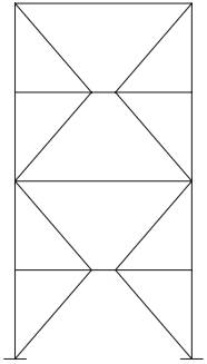
Figure description:
Key Information:
- System Type: Two-story-X Eccentrically Braced Frame (EBF configuration.
- Key Entities:
- Vertical Columns: Two main load-bearing members on the sides.
- Horizontal Beams: Members connecting the columns at three levels.
- Diagonal Braces: Arranged in an "X" pattern within each story.
- Links: Short horizontal segments in the center of the beams created by the eccentric connection of the diagonal braces.
- Purpose: A seismic-resistant structural design where the links are intended to yield and dissipate energy to protect the columns and other primary members.
Fig. C-F3.3. Two-story-X EBF configuration (Engelhardt and Popov, 1989a).
developed for estimating such reduced forces on the basis of a linear analysis; designers may elect to perform a nonlinear analysis in accordance with Chapter C.
In addition to the requirements of this section, columns in EBF must also be checked in accordance with the requirements of Section D1.4a, which are applicable to all systems.
Tests showed (Berman and Bruneau, 2006, 2008b, 2008c) that strain hardening is larger for links with built-up box cross sections than for I-shaped links. Comparing the overstrength obtained for box links to that obtained for I-shaped links by Richards (2004), Berman and Bruneau indicated that built-up rectangular box links have a maximum strength typically larger than I-shaped links. The forces to consider for the design of the braces, beams outside the link, and columns are therefore increased accordingly.
F3.4 System Requirements
F3.4a Link Rotation Angle
The total link rotation angle is the basis for controlling tests on link-to-column connections, as described in Section K2.4c. In a test specimen, the total link rotation angle is computed by simply taking the relative displacement of one end of the link with respect to the other end and dividing by the link length. The total link rotation angle reflects both elastic and inelastic deformations of the link, as well as the influence of link end rotations. While the total link rotation angle is used for test control, acceptance criteria for link-to-column connections are based on the link inelastic rotation angle.
To ensure satisfactory behavior of an EBF, the inelastic deformation expected to occur in the links in a severe earthquake should not exceed the inelastic deformation capacity of the links. In the Provisions, the link rotation angle is the primary variable used to describe inelastic link deformation. The link rotation angle is the plastic rotation angle between the link and the portion of the beam outside of the link.
The link rotation angle can be estimated by assuming that the EBF bay will deform in a rigid-plastic mechanism as illustrated for various EBF configurations in Figure C-F3.4. In this figure, the link rotation angle is denoted by the symbol . The link rotation angle can be related to the plastic story drift angle, , using the relationships shown in Figure C-F3.4. The plastic story drift angle, in turn, can be computed as the plastic story drift, , divided by the story height, . The plastic story drift is equal to the difference between the drift corresponding to the design earthquake displacement and the elastic drift. Alternatively, the link rotation angle can be determined more accurately by inelastic dynamic analyses.
The inelastic response of a link is strongly influenced by the length of the link as related to the ratio, , of the link cross section. When the link length is selected not greater than , shear yielding will dominate the inelastic response. If the link length is selected greater than , flexural yielding will dominate the inelastic response. For link lengths intermediate between these values, the inelastic response will occur through some combination of shear and flexural yielding. The inelastic deformation capacity of links is generally greatest for shear yielding links and smallest for flexural yielding links. Based on experimental evidence, the link rotation angle is limited to 0.08 rad for shear yielding links, , and 0.02 rad for flexural yielding links, . For links in the combined shear and flexural yielding range, , the limit on link rotation angle is determined according to link length by linear interpolation between 0.08 and 0.02 rad.
It has been demonstrated experimentally (Whittaker et al., 1987; Foutch, 1989) as well as analytically (Popov et al., 1989) that links in the first floor usually undergo the largest inelastic deformation. In extreme cases, this may result in a tendency to develop a soft story. The plastic link rotations tend to attenuate at higher floors and decrease with the increasing frame periods. Therefore, for severe seismic applications, a conservative design for the links in the first two or three floors is recommended. This can be achieved by providing links with an available shear strength at least 10% over the required shear strength.
F3.4b Bracing of Link
Lateral restraint against out-of-plane displacement and twist is required at the ends of the link to ensure stable inelastic behavior. This section specifies the required strength and stiffness of link-end lateral bracing. In typical applications, a composite deck
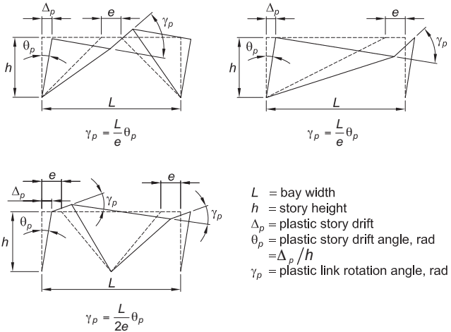
Figure description:
Figure Title: Fig. C-F3.4. Link rotation angle
Variable Definitions:
- : bay width
- : story height
- : plastic story drift
- : plastic story drift angle (rad
- : plastic link rotation angle (rad
- : link length
Plastic Link Rotation Formulas:
- Single central or end link configurations:
- Dual link configuration:
Fig. C-F3.4. Link rotation angle.
can likely be counted upon to provide adequate lateral bracing at the top flange of the link. However, a composite deck alone cannot be counted on to provide adequate lateral bracing at the bottom flange of the link and direct bracing through transverse beams or a suitable alternative is required.
A link with a built-up box cross section, tested without lateral bracing in a full EBF configuration, exhibited no lateral-torsional buckling (Berman and Bruneau, 2007). Slender box cross sections (significantly taller than wide) could develop lateral-torsional buckling, but the unbraced length required to do so for such sections is still considerably longer than for wide-flange links. As a result, except for unusual aspect ratios, links with built-up box cross sections will not require lateral bracing.
F3.5 Members
F3.5a Basic Requirements
The ductility demands in EBF are concentrated in the links. Braces, columns, and beams outside the link should have very little yielding in a properly designed EBF. If the brace is designed to be stronger than the link, as is the intent of these provisions, the link will serve as a fuse to limit the maximum load transferred to the brace, thereby precluding the possibility of brace buckling. Consequently, many of the design provisions for braces in SCBF systems intended to permit stable cyclic buckling of braces are not needed in EBF. Similarly, the link also limits the loads transferred to the beam beyond the link, thereby precluding failure of this portion of the beam if it is stronger than the link.
For most EBF configurations, the beam and the link are a single continuous I-shaped member. If this is the case, the available strength of the beam can be increased by . If the link and the beam are the same member, any increase in yield strength present in the link will also be present in the beam segment outside of the link.
F3.5b Links
Inelastic action in EBF is intended to occur primarily within the links. The general provisions in this section are intended to ensure that stable inelasticity can occur in the link.
At brace connections to the link, the link length is defined by the edge of the brace connection as shown in Figure C-F3.5. Bracing using hollow structural section (HSS) members is shown in Figure C-F3.6. Brace connection details employing gussets are commonly configured so that the gusset edge aligns vertically with the intersection of the brace and beam centerlines. For brace connections not employing gussets, the intersection of the brace at the link end may not align vertically with the intersection of the brace and beam centerlines; the intersection of centerlines may fall within the link (Figure C-F3.5) or outside of the link (Figure C-F3.7). In either case, flexural forces in the beam outside the link and the brace may be obtained from an analysis that models the member centerline intersections, provided that the force level in the analysis corresponds to the expected strain-hardened link capacity as required by Section F3.3. However, such a centerline analysis will not produce correct link end-moments. See Commentary Section F3.5b.1. Link end-moments for either case can more accurately be obtained using the following equation:
(C-F3-8)
where is the link beam shear in the condition under consideration, whether it be corresponding to the design base shear or to the fully yielded, strain-hardened link as required in Section F3.3.
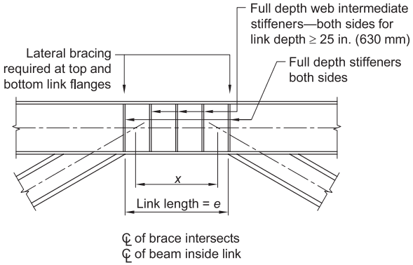
Figure description:
Entity: Eccentrically Braced Frame (EBF with I-shape bracing (x < e
- Link Length (: The defined length of the eccentric link between the brace connection points.
- Brace Intersection (: The distance between the points where brace centerlines intersect the beam centerline, occurring within the link (.
- Lateral Bracing: Required at both the top and bottom flanges at each end of the link.
- Stiffeners:
- End Stiffeners: Full depth stiffeners on both sides at the ends of the link.
- Intermediate Stiffeners: Full depth web intermediate stiffeners on both sides required for link depths in ( mm.
- Alignment: The centerline of each brace intersects the beam centerline inside the link.
Fig.C-F3.5. EBF with I-shape bracing (x < e).
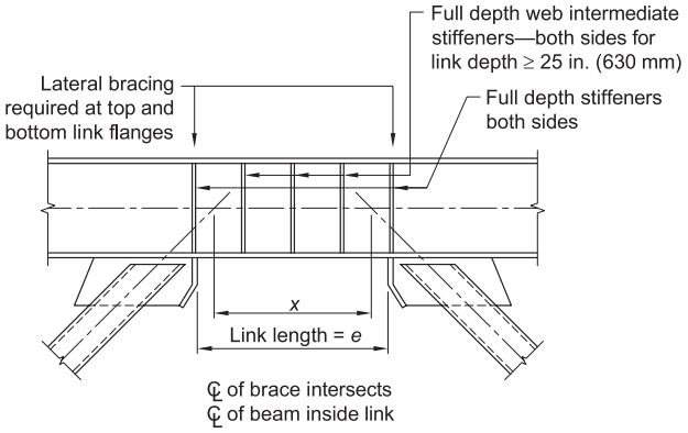
Figure description:
Structural Diagram: Eccentrically Braced Frame (EBF Detail
-
Key Entities:
- Beam: Horizontal structural member containing the link.
- Link: The segment of the beam between the brace connections, defined by length .
- Braces: Diagonal structural members (I-shape or HSS intersecting the beam.
- Full Depth Stiffeners: Placed on both sides at the ends of the link.
- Full Depth Web Intermediate Stiffeners: Placed on both sides within the link if link depth .
- Lateral Bracing: Required at both top and bottom link flanges at the ends of the link.
-
Key Dimensions & Geometric Relationships:
- : The distance between the intersection points of the brace centerlines and the beam centerline.
- Condition: (Brace centerlines intersect the beam centerline inside the link.
- Centerline (: The centerline of the brace intersects the centerline of the beam inside the link.
Fig. C-F3.6. EBF with HSS bracing (x < e).
However, link end moments are not directly used in selecting the link member in the typical design procedure. Section F3.5b.2 converts link flexural strength to an equivalent shear strength based on link length. Comparison of that equivalent shear strength to the required shear strength is sufficient for design and the results of a centerline model analysis can be used without modification.
F3.5b.1 Limitations
Width-to-thickness limits for links are specified in Table D1.1. Early editions of the Provisions required the link cross section to meet the same width-to-thickness criteria as is specified for beams in special moment frames (SMF), which corresponded to the highly ductile requirements. Based on research on local buckling in links (Okazaki et al., 2004a; Richards et al., 2004), the flange width-to-thickness limits for links are only required to meet the compactness limits for moderately ductile members, which corresponds to in Specification Table B4.1b. The exception in this section permits a relaxation on the requirements for flanges of links for I-shaped sections, allowing them to be moderately ductile for length . Limits on slenderness of link built-up box sections are provided to prevent links that are significantly taller than wide (that could develop lateral-torsional buckling). Based on research by Berman and Bruneau (2008b, 2008c), the Provisions also permit relaxation for webs of links for built-up box sections with link lengths , where the web width-to-thickness ratio is limited to , as given in Table D1.1b for moderately ductile members. For built-up box-section links with link lengths , the web width-to-thickness ratio is limited to for highly ductile members. Specimens with links other than at mid-width of the braced bay have not been tested.
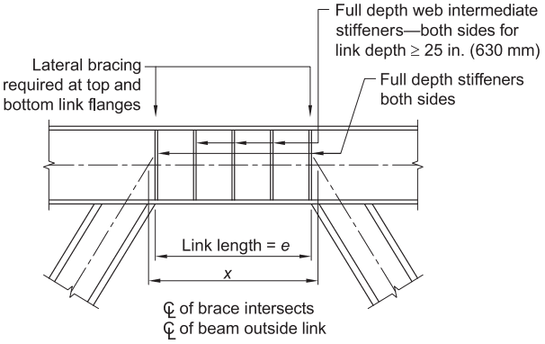
Figure description:
Key Information:
- Subject: Eccentrically Braced Frame (EBF with I-shape bracing where .
- Link Length (: Defined as the distance between the centerlines of the braces at the level of the beam.
- Stiffeners:
- Full depth stiffeners: Required on both sides at each end of the link.
- Full depth web intermediate stiffeners: Required on both sides for link depths in. (630 mm.
- Bracing: Lateral bracing is required at both the top and bottom link flanges at the link ends.
- Geometry: The centerline ( of the brace intersects the centerline ( of the beam outside the link area.
Fig. C-F3.7. EBF with I-shape bracing (x > e).
The reinforcement of links with web doubler plates is not permitted as such reinforcement may not fully participate as intended in inelastic deformations. Additionally, beam web penetrations within the link are not permitted because they may adversely affect the inelastic behavior of the link.
The 2005 Provisions (AISC, 2005) required that the intersection of the beam and brace centerlines occur at the end of the link or inside of the link. The reason for this restriction was that when the intersection of the beam and brace centerlines occurs outside of the link, additional moment is generated in the beam outside of the link. However, locating the intersection of the beam and brace centerline outside of the link is sometimes unavoidable for certain member sizes and brace connection geometries. Further, it is acceptable to locate the intersection outside of the link, as long as the additional moment in the beam is considered in the design. Consequently, the restriction has not been part of the Provisions since 2010.
When the distance between intersection of the beam and brace centerlines, , exceeds the link length, , as is shown in Figure C-F3.7, the total moment resisted by the beam outside the link and the brace (if moment-connected) exceeds the link end moment. Conversely if the link length, , exceeds the distance between the intersection of the beam and brace centerlines, , as is shown in Figures C-F3.5 and C-F3.6, the link end moment at the design level will exceed the forces indicated using a centerline model. In both conditions, care should be taken to ensure sufficient strength at the design level and proper estimation of forces in the beam outside the link and in the brace at drifts corresponding to a fully yielded, strain-hardened link.
F3.5b.2 Shear Strength
The nominal shear strength of the link, , is the lesser of that determined from the plastic shear strength of the link section or twice the plastic moment divided by the link length, as dictated by statics assuming equalization of end moments in the inelastic range of behavior. Accordingly, the nominal shear strength of the link can be computed as follows:
(C-F3-9)
The effects of axial load on the link can be ignored if the required axial strength of the link does not exceed 15% of the axial yield strength of the link, . In general, such an axial load is negligible because the horizontal component of the brace load is transmitted to the beam segment outside of the link. However, when the framing arrangement is such that larger axial forces can develop in the link, such as from drag struts or a modified EBF configuration, the available shear strength and the length of the link are reduced (according to Sections F3.5b.2 and F3.5b.3, respectively).
F3.5b.3 Link Length
The rotations that can be achieved in links subjected to flexural yielding with high axial forces have not been adequately studied. Consequently, where high axial forces can develop in the link, its length is limited to ensure that shear yielding, rather than flexural yielding, governs to ensure stable inelastic behavior.
F3.5b.4 Link Stiffeners for I-Shaped Cross Sections
A properly detailed and restrained link web can provide stable, ductile, and predictable behavior under severe cyclic loading. The design of the link requires close attention to the detailing of the link web thickness and stiffeners. Full-depth stiffeners are required at the ends of all links and serve to transfer the link shear forces to the reacting elements as well as restrain the link web against buckling.
The maximum spacing of link intermediate web stiffeners in shear yielding links, , is dependent upon the size of the link rotation angle (Kasai and Popov, 1986b) with a closer spacing required as the rotation angle increases. Intermediate web stiffeners in shear yielding links are provided to delay the onset of inelastic shear buckling of the web. Flexural yielding links having lengths greater than or equal to but less than are required to have an intermediate stiffener at a distance from the link end equal to 1.5 times the beam flange width to limit strength degradation due to flange local buckling and lateral-torsional buckling. Links of a length that are between the shear and flexural limits are required to meet the stiffener requirements for both shear and flexural yielding links. When the link length exceeds , link intermediate web stiffeners are not required. Link intermediate web stiffeners are required to extend full depth to effectively resist shear buckling of the web and to effectively limit strength degradation due to flange local buckling and lateral-torsional buckling. Link intermediate web stiffeners are required on both sides of the web for links 25 in. (630 mm) in depth or greater. For links that are less than 25 in. (630 mm) deep, the stiffener need be on one side only.
All link stiffeners are required to be fillet welded to the link web and flanges. Link stiffeners should be detailed to avoid welding in the -area of the link. Research has indicated that stiffener-to-link web welds that extend into the -area of the link can generate link web fractures that may reduce the plastic rotation capacity of the link (Okazaki et al., 2004a; Richards et al., 2004).
F3.5b.5 Link Stiffeners for Box Sections
Similar to I-shaped links, the maximum spacing of stiffeners for shear yielding built-up box-section links, , is dependent upon the magnitude of the link rotation angle. The equation for maximum spacing needed for the links to develop a link rotation angle of 0.08 rad, specified as , is derived in Berman and Bruneau (2005a). A similar equation was also derived for a 0.02 rad limit, resulting in a maximum required stiffener spacing of . However, experimental and analytical data are only available to support the closer stiffener spacing required for the 0.08 rad link rotation angle; therefore, the more restrictive stiffener spacing is required for all links until other data becomes available.
The use of intermediate web stiffeners was shown (Berman and Bruneau, 2006, 2008b, 2008c) to have a significant effect on the shear yielding strength in built-up box links with greater than and less than or equal to . For shear links with less than or equal to , flange buckling was the controlling limit state, and intermediate stiffeners had no effect. Thus, intermediate web stiffeners are not required for links with web depth-to-thickness ratios less than . For links with lengths exceeding , compression local buckling of both webs and flanges (resulting from the compressive stresses associated with the development of the plastic moment) dominated link strength degradation. This buckling was unaffected by the presence of intermediate web stiffeners. As a result, intermediate web stiffeners are not required for links with lengths exceeding .
When intermediate stiffeners were used in the built-up box section tested and simulated numerically by Berman and Bruneau (2006, 2008b, 2008c), these stiffeners were welded to both the webs and the flanges. A typical cross section is shown in Figure C-F3.8. However, presence of the stiffeners did not impact flange buckling, and these may therefore not need to be connected to the flange. This would have advantages over the detail in Figure C-F3.8. In particular, the intermediate stiffeners could be fabricated inside the built-up box-section link, improving resistance to corrosion and risk of accumulation of debris between the stiffeners (in cases of exterior exposures) and enhancing architectural appeal. Review of the literature (Malley and Popov, 1983; Bleich, 1952; Salmon and Johnson, 1996) showed that the derivation of minimum required areas and
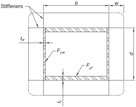
Figure description:
Entities and Dimensions:
- Box Section: A rectangular built-up cross section consisting of two vertical webs and two horizontal flanges.
- Stiffeners: External plates projecting from the corners of the box section.
- : Width of the box section between the inner faces of the vertical stiffeners.
- : Depth of the box section.
- : Width/extension of the external stiffeners.
- : Thickness of the web plates.
- : Thickness of the flange plates.
- : Yield strength of the web material.
- : Yield strength of the flange material.
Fig. C-F3.8. Built-up box-section link cross section with intermediate stiffener.
moment of inertia equations for sizing intermediate stiffeners did not depend on connection to the flanges. Whereas web stiffeners in I-shaped links may also serve to provide stability to the flanges (Malley and Popov, 1983), this is not the case in built-up box sections. Thus, welding of intermediate stiffeners to the flanges of the built-up box-section links is not critical and not required.
F3.5c Protected Zones
The link, as the expected region of inelastic strain, is a protected zone.
F3.6 Connections
F3.6a Demand Critical Welds
Inelastic strain in the weld material is likely at column base plates, at column splices, and in moment connections in eccentrically braced frames. In addition, inelastic strain is likely in welds of a built-up link member; thus, these are required to be treated as demand critical welds. See Commentary Section F2.6a.
F3.6b Beam-to-Column Connections
See Commentary Section F2.6b.
F3.6c Brace Connections
In the 2005 Provisions, the brace connection was required to be designed for the same forces as the brace, which are the forces generated by the fully yielded and strain-hardened link. The brace connection, however, was also required to be designed for a compressive axial force corresponding to the nominal buckling strength of the brace. This second requirement was eliminated in 2010. Braces in EBF are designed to preclude buckling, and it is considered unnecessarily conservative to design the brace connection for the buckling strength of the brace.
Bracing connections are required to be designed to resist forces corresponding to link yielding and strain hardening. The strain-hardening factors used in Section F3.3— 1.25 for I-shaped links and 1.4 for box links—are somewhat low compared to some values determined from testing; however, the reliability of connections remains sufficient due to the use of lower resistance factors for nonductile limit states.
Bolt slip is not a limit state that must be precluded. The consequences of exceeding this limit state in the maximum credible earthquake are not considered severe if bearing failure and block shear rupture are precluded.
A few EBF link fractures were observed following the Christchurch earthquake series of 2010 and 2011 (Clifton et al., 2011). Finite element analyses conducted to investigate this behavior revealed that when braces frame into the link beam and no gusset is used, eccentricity (misalignment) of link stiffeners with respect to the beam-to-brace flange connection point can lead to severe local ductility demands and premature failures outside of the link (Imani and Bruneau, 2015; Kanvinde et al., 2014), as shown in Figure C-F3.9. For cases where modifying the brace section to achieve the preceding condition is not possible, analyses showed that moving the link stiffener to eliminate the offset between the end stiffener and beam-to-brace flange connection point can be effective to improve the overall behavior of the EBF frame, even if the intersection of the brace-to-beam centerlines falls inside the link (Imani and Bruneau, 2015).
F3.6d Column Splices
See Commentary Section F2.6d.
F3.6e Link-to-Column Connections
Prior to the 1994 Northridge earthquake, link-to-column connections were typically constructed in a manner substantially similar to beam-to-column connections in SMF. Link-to-column connections in EBF are, therefore, likely to share many of the same problems observed in moment-frame connections. Consequently, in a manner similar to beam-to-column connections in SMF, the Provisions require that the performance of link-to-column connections be verified by testing in accordance with Section K2
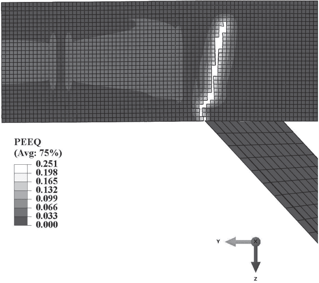
Figure description:
Subject: Simulated fracture at the offset between a link stiffener and brace flange in an Eccentrically Braced Frame (EBF connection.
Key Components:
- Structural Elements: Horizontal link member with a vertical stiffener and an angled brace flange connected at the bottom.
- Simulation Detail: A vertical crack/fracture is visible through the horizontal member, originating near the brace connection point.
- Measurement: Equivalent Plastic Strain (PEEQ shown via a grayscale gradient on a finite element mesh.
- Coordinate System: Y-axis (pointing left, Z-axis (pointing down, X-axis (pointing out of plane.
PEEQ Legend Data:
| PEEQ (Avg: 75%) |
|---|
| 0.251 |
| 0.198 |
| 0.165 |
| 0.132 |
| 0.099 |
| 0.066 |
| 0.033 |
| 0.000 |
Fig. C-F3.9. Simulated fracture at offset between link stiffener and brace flange from Imani and Bruneau (2015).
or by the use of prequalified link-to-column connections in accordance with Section K1; there are no prequalified connections at the time of publication.
The load and deformation demands at a link-to-column connection in an EBF are substantially different from those at a beam-to-column connection in an SMF. Designers are cautioned that beam-to-column connections that qualify for use in an SMF may not necessarily perform adequately when used as a link-to-column connection in an EBF. Link-to-column connections must therefore be tested in a manner that properly simulates the forces and inelastic deformations expected in an EBF. For example, the reduced beam section (RBS) connection has been shown to perform well in an SMF. However, the RBS is generally not suitable for link-to-column connections due to the high moment gradient in links. Similarly, research (Okazaki, 2004; Okazaki et al., 2004b) has demonstrated that other details that have shown good performance in moment frame beam-to-column connections [such as the welded unreinforced flange-welded web (WUFW) and the free flange details] can show poor performance in EBF link-to-column connections.
The Provisions permit the use of link-to-column connections without the need for qualification testing for shear yielding links when the connection is reinforced with haunches or other suitable reinforcement designed to preclude inelastic action in the reinforced zone adjacent to the column. An example of such a connection is shown in Figure C-F3.10. This reinforced region should remain essentially elastic for the fully yielded and strain-hardened link strength as required by Section F3.3; the exception for beams outside links does not apply. That is, the reinforced connection should be designed to resist the link shear and moment developed by the expected shear strength of the link, , multiplied by 1.25 to account for strain hardening. As an alternative to the reinforced link-to-column connection detail illustrated in Figure C-F3.10, preliminary testing and analysis have shown very promising performance
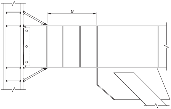
Figure description:
- Subject: Structural diagram of a reinforced link-to-column connection in an eccentrically braced frame (EBF.
- Key Entities:
- Vertical Column: Primary vertical support on the left.
- Link Beam: Horizontal member connecting the column to the brace; contains the designated link length (.
- Reinforcement Haunches: Triangular plates at the top and bottom of the link-to-column interface designed to protect the connection from inelastic action.
- Web Stiffeners: Vertical plates spaced within the link length to prevent web buckling.
- Eccentric Brace: Partial view of the diagonal brace connected to the beam at the right end of the link.
- Bolted/Welded Connection: Interface details between the beam web and the column flange.
Fig. C-F3.10. Example of a reinforced link-to-column connection.
for a reinforced connection detail wherein a pair of stiffeners is provided in the first link web panel next to the column, with the stiffeners oriented parallel to the link web. This link-to-column connection detail is described in Okazaki et al. (2009). Alternatively, the EBF can be configured to avoid link-to-column connections entirely.
The Provisions do not explicitly address the column panel-zone design requirements at link-to-column connections. Based on limited research (Okazaki, 2004), it is recommended that the panel zone of link-to-column connections be designed in a manner similar to that for SMF beam-to-column connections with the required shear strength of the panel zone determined from the analysis required by Section F3.3.