The composite special concentrically braced frame (C-SCBF) is one of two types of composite braced frames that are specially detailed for seismic design categories D, E, and F; the other is the composite eccentrically braced frame (C-EBF). While experience using C-SCBF is limited in high seismic regions, the design provisions for C-SCBF are intended to provide behavior that is comparable to structural steel
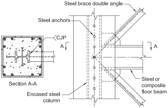
Figure description:
Diagram Type: Structural engineering detail of a reinforced concrete/composite column-to-steel concentric brace.
Key Components:
- Encased Steel Column: A central steel I-beam embedded within a square reinforced concrete column.
- Steel Brace Double Angle: Diagonal bracing members connected to the column junction.
- Steel or Composite Floor Beam: Horizontal structural member intersecting the column and brace connection.
- Steel Anchors: Vertical series of studs/connectors along the encased steel column flange.
- Section A-A: Cross-section showing the internal layout of the composite column, including longitudinal rebar, ties, and the CJP (Complete Joint Penetration weld location.
- Gusset Plate: Connection plate joining the braces and floor beam to the column.
Fig. C-H1.1. Reinforced concrete (or composite) column-to-steel concentric brace.
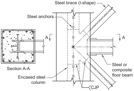
Figure description:
Key Entities and Information:
- Subject: Structural detail of a reinforced concrete (or composite column-to-steel concentric brace connection.
- Encased Steel Column: An internal steel I-beam section embedded within a reinforced concrete column.
- Steel Brace (I-shape: Diagonal bracing members with an I-shaped cross-section.
- Steel or Composite Floor Beam: A horizontal structural member intersecting at the column-brace joint.
- Steel Anchors: Headed studs or anchors attached to the encased steel column to ensure composite action with the surrounding concrete.
- CJP Welds: Complete Joint Penetration welds are specified at the brace-to-gusset/column interfaces.
- Section A-A: A cross-sectional view showing the reinforced concrete details, including longitudinal rebar, ties, and the orientation of the encased steel column.
Fig. C-H1.2. Reinforced concrete (or composite) column-to-steel concentric brace.
SCBF, wherein the braces often are the primary yielding elements, and therefore, most susceptible to inelastic deformations. See Commentary Section F2 for further discussion of the expected response of SCBF. Values and usage limitations for the seismic response modification coefficient, , and deflection amplification factor, , for C-SCBF are similar to those for steel SCBF.
H2.1 Scope
Unlike C-OBF, which permit the use of reinforced concrete columns, the scope for C-SCBF is limited to systems with composite columns so that there will be a reliable force transfer from the steel or composite braces and beams into the columns.
- Basis of Design
The basis of design is comparable to steel SCBF. Thus, the provisions for analysis, system requirements, members, and brace connections make reference to the provisions of Section F2. Refer to the associated Commentary for Section F2 where reference is made to that section in the Provisions.
H2.3 Analysis
Just as the SCBF requires the system to be designed for the brace member tensile capacity and the cyclic post-buckling behavior, so does the composite system. Composite braces can develop higher forces than the steel brace member itself, due to compressive capacity of the concrete area as well as tension capacity of developed longitudinal reinforcement in the concrete. The maximum loads the connection may be required to resist should consider the concrete and reinforcing steel overstrength.
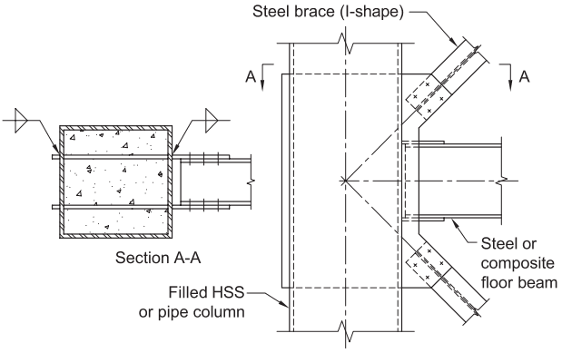
Figure description:
Key Information:
- Subject: Filled HSS (Hollow Structural Section or pipe column-to-steel concentric brace connection.
- Main Components:
- Column: Concrete-filled HSS or pipe.
- Brace: Steel I-shape brace.
- Beam: Steel or composite floor beam.
- Connection Details:
- Concentric connection where the centerlines of the brace, beam, and column intersect.
- Section A-A: Cross-section showing the internal concrete fill and gusset plate connection passing through or welded to the HSS wall.
- Gusset Plate: Connects the steel brace and floor beam to the vertical column.
Fig. C-H1.3. Filled HSS or pipe column-to-steel concentric base.
H2.4 System Requirements
Multi-tiered braced frames (MTBF) are permitted for C-SCBF consistent with the scope of this section, with the exception that composite braces are not permitted for MTBF as there is insufficient basis for developing appropriate strength and stiffness requirements for composite braces in MTBF.
H2.5 Members
Composite columns in C-SCBF are detailed with similar requirements to highly ductile composite columns in composite special moment frames (C-SMF). Special attention should be paid to the detailing of the connection elements (MacRae et al., 2004).
H2.5b Diagonal Braces
Braces that are all steel should be designed to meet all requirements for steel braces in Section F2.
In cases where composite braces are used, either filled or encased, the concrete has the potential to stiffen the steel section and prevent or delay brace buckling while, at the same time, increasing the capability to dissipate energy. The filling of hollow structural sections (HSS) with concrete has been shown to effectively stiffen the HSS walls and inhibit local buckling (Goel and Lee, 1992). For encased steel braces, the concrete should be sufficiently reinforced and confined to prevent the steel shape from buckling. To provide high ductility, the composite braces are required to be designed to meet all requirements for encased composite columns as specified in Section D1.4b. Composite braces in tension should be designed based on the steel section alone unless tests justify higher strengths.
H2.6 Connections
Careful design and detailing of the connections in a C-SCBF are required to prevent connection failure before developing the full strength of the braces in either tension or compression. Where the brace is composite, the added brace strength afforded by the concrete should be considered in the connection design. In such cases, it would be unconservative to base the connection strength on the steel section alone. Connection design and detailing should recognize that buckling of the brace could cause excessive rotation at the brace ends and lead to local connection failure. Therefore, as in steel SCBF, the brace connection should either be designed to accommodate the inelastic rotations associated with brace buckling or to have sufficient strength and stiffness to accommodate plastic hinging of the brace adjacent to the connection.
H2.6a Demand Critical Welds
For general commentary on demand critical welds, see Commentary Section A3.4.
H2.6b Beam-to-Column Connections
Ductile connections between the beam and column are required for C-SCBF. Rotation requirements for simple connections are provided. See Commentary Section F2.6b for further discussion.
H2.6d Column Splices
The requirements for column splices are comparable to those of C-IMF. Refer to Commentary Section G2.6f.