H4.1 Scope
This section applies to reinforced concrete shear walls with composite boundary elements, as shown in Figure C-H4.1, and coupled reinforced concrete walls, with or without composite boundary elements, in which structural steel or composite coupling beams connect two or more adjacent walls, as shown in Figure C-H4.2.
Structural steel or composite boundary elements may be used as wall boundary elements or for erection purposes only. In the latter case, the structural steel members may be relatively small. The detailing of coupling beam-to-wall connections depends
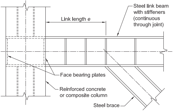
Figure description:
Structural Diagram: Reinforced Concrete or Composite Column-to-Steel Eccentric Brace
- Reinforced Concrete or Composite Column: Vertical support member containing embedded steel components.
- Steel Link Beam: Horizontal member with internal stiffeners, continuous through the column joint.
- Steel Brace: Diagonal member connected to the link beam at the end of the link length.
- Link Length (: Specified horizontal distance from the column face to the center of the brace connection.
- Face Bearing Plates: Located at the column face and embedded within the column to transfer loads.
- Stiffeners: Vertical internal plates within the steel link beam, designed per Section F3.5a.
Fig. C-H3.1. Reinforced concrete (or composite) column-to-steel eccentric brace. (Note: Stiffeners are designed according to Section F3.5a.)
on whether structural shapes are embedded in the wall boundaries or the wall has conventional reinforced concrete boundary elements. If steel or composite column boundary elements are used, the coupling beams can frame into the columns and transfer the coupling forces through a moment connection with the steel column as shown in Figure C-H4.3(a). The use of a moment connection is, however, not preferred given the cost and difficulty of constructing ductile connections. Alternatively, the coupling beam may be connected to the embedded boundary column with a shear connection where the coupling beam moment, vertical shear, and axial force are resisted in a manner similar to cases without an embedded column by a combination of bearing along the embedment length, horizontal shear transfer provided by steel anchors along the coupling beam flanges, and the steel shear connection as shown in Figure C-H4.3(b).
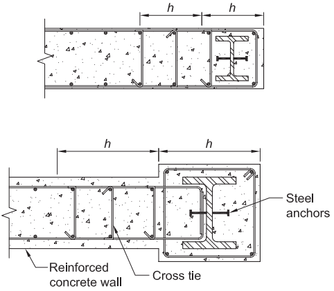
Figure description:
Key Entities and Information:
- Reinforced Concrete Walls: Structural wall sections featuring longitudinal and transverse reinforcement.
- Composite Boundary Elements: Embedded structural steel shapes (I-beams/W-shapes positioned at the wall ends to enhance strength and ductility.
- Steel Anchors: Mechanical connectors attached to the web of the embedded steel shape to facilitate shear transfer.
- Cross Ties: Transverse reinforcement bars securing longitudinal rebar within the wall.
- Configuration Variants:
- Flush Boundary: The boundary element thickness matches the wall thickness.
- Enlarged Boundary: the boundary element section is wider than the main wall thickness.
- Dimension 'h': Defines specific reinforcement zones and spacing intervals within the boundary region.
Fig. C-H4.1. Reinforced concrete walls with composite boundary element.
Coupling beams
Fig. C-H4.2. Examples of coupled wall geometry.
If structural steel or composite boundary elements are not present, the coupling beam should be embedded a sufficient distance into the wall so that the coupling forces are transferred entirely through the interaction that occurs between the embedded coupling beam and the surrounding reinforced concrete.
H4.2 Basis of Design
The level of inelastic deformation in C-OSW is limited. Equations H4-4 and H4-4M predict the shear strength of the beam-to-wall connection and inherently provide the required flexural strength through interaction of the embedded portion of the beam with the surrounding concrete. Equations H4-6 and H4-6M allow for yielding and implicit ductility in shear. It is, thus, expected that the requirements of Specification Section G2 will be satisfied such that in the calculation of the nominal
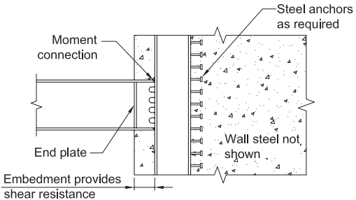
Figure description:
Key Entities and Details:
- Steel Coupling Beam: Horizontal element attached to the wall via a moment connection and an end plate.
- Steel Wall Boundary Element Column: Vertical steel member embedded within the concrete wall.
- Concrete Wall: Reinforced structure housing the boundary element; wall reinforcement steel is noted as not shown.
- Steel Anchors: Headed studs attached to the boundary element, embedded in concrete as required.
- Embedment Zone: Specified area where the beam's integration provides shear resistance.
- Connection Type: Moment connection between the coupling beam and the boundary element.
(a) Steel coupling beam attached to steel wall boundary element column
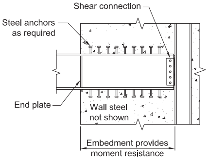
Figure description:
- Subject: Structural detail of a steel coupling beam embedded in a concrete wall.
- Key Components:
- Steel coupling beam: Horizontal member extending into the wall.
- Steel anchors: Attached along the top and bottom flanges within the embedment zone.
- End plate: Positioned at the face of the concrete wall.
- Shear connection: Bolted plate connecting the end of the beam to a vertical steel column.
- Embedment: The embedded length is specified to provide moment resistance.
- Notes: Wall reinforcement (steel is not shown in the diagram.
(b) Steel coupling beam attached to steel erection column
Fig. C-H4.3. Steel coupling beam details.
shear strength of a steel beam within a composite coupling beam. For a composite coupling beam, the minimum shear reinforcement requirements from ACI 318 (ACI, 2019) are satisfied. The wall piers are to be designed based on nonseismic provisions of ACI 318; however, the requirements of Chapter 18 do not have to be satisfied for these ordinary systems.
H4.3 Analysis
In order to compute the design forces and deformations, the wall piers need to be modeled considering uncracked section properties for concrete, and the composite coupling beams need to be modeled considering cracked section properties for concrete. Guidance from ACI 318 (ACI, 2019), Chapter 6 (Sections 6.6.3.1.1, 6.6.4.2, 6.7.1.3), and ASCE 41 (ASCE, 2017) is available for wall piers.
Modeling of the wall piers falls into three main classes, in increasing degree of complexity: (a) equivalent frame models, (b) multi-spring models, and (c) continuum finite element models (ASCE, 2009). Previous studies (Shahrooz et al., 1993; Harries et al., 1997; Gong and Shahrooz, 2001b; Motter et al., 2017) have demonstrated that steel or steel-concrete composite coupling beams do not have a fully fixed boundary condition at the face of the wall. The Provisions account for the additional flexibility when used in equivalent frame or multi-spring models to ensure that wall forces and lateral deflections are computed with reasonable accuracy when coupling beam clear spans are used in analysis. If the embedment length of the beam is known, the effective fixed point of steel or steel-concrete composite coupling beams may alternatively be taken at one-third of the embedment length from the face of the wall (Shahrooz et al., 1993; Gong and Shahrooz, 2001b). Thus, the effective span of the equivalent fixed-end beam used for analysis, , is , where is the clear span and is the embedment length. When is used, the composite coupling beam stiffness values in Section H4.3(a) should be increased by a factor of for flexure and for shear. If the value of is not available, the procedure proposed by Harries et al. (1997) may be used. In this procedure, the effective flexural stiffness, reduced to account for the presence of shear, of a steel coupling beam is reduced to of its gross section value:
(C-H4-1)
where
area of steel section assumed to resist shear, which is typically the area of the steel web, in.
- modulus of elasticity of steel, ksi (MPa)
- shear modulus of steel, ksi (MPa)
- moment of inertia of steel coupling beam, in.
= cross-section shape factor for shear (1.5 for W-shapes)
If the computer model accounts for the effects of shear deformation, is taken as .
H4.3.5 Members
H4.3.5b Coupling Beams
Coupling beam response is intended to be similar to shear link response in EBF. The expected coupling beam chord rotation plays an important role in how the coupling beam is detailed. This angle may be computed from
(C-H4-2)
where
- = distance between the centroids of the wall piers, in. (mm)
- effective clear span as discussed in Commentary Section H4.3, in. (mm)
- = story drift angle, computed as the story drift divided by the story height, rad (Harries et al., 2000)
For cases in which the coupling beam embedment into the wall piers is the only mechanism of moment resistance, the embedment length has to be long enough to develop the required shear demand determined from structural analysis that considers all the applicable load combinations. Models have been developed for connections between steel brackets and reinforced concrete columns (e.g., Mattock and Gaafar, 1982). These models are used to compute an embedment length required to prevent bearing failure of concrete surrounding the flanges of the embedded steel members. A number of studies (Shahrooz et al., 1993; Gong and Shahrooz, 2001a, 2001b; Fortney, 2005; Motter et al, 2017) have demonstrated the adequacy of Mattock and Gaafar’s model for coupling beams subjected to reversed cyclic loading. Other models (Harrries et al., 1997) may also be used. Equations H4-4 and H5-1 (H4-4M and H5-1M) are based on the model developed by Mattock and Gaafar (1982) and recommended by ASCE (2009). The strength model in these equations is intended to mobilize the moment arm, , between bearing forces and shown in Figure C-H4.4.
A parabolic distribution of bearing stresses is assumed for , and is estimated by a uniform stress equal to
(C-H4-3)
where
The term accounts for spreading of the compressive stress beneath the beam flange as shown in Section A-A of Figure C-H4.4 and was calibrated based on experimental data. In Equations H4-4 and H4-4M, the ratio and shown in Figure C-H4.4 are assumed to be 0.66 and 0.36 , respectively, as recommended by Mattock and Gaafar (1982). The parameter, shown in Figure C-H4.4, is the parameter,
, used by Mattack and Gaafar to define one-half the effective span of the coupling beam.
Amplification of accounts for a longer effective coupling beam span and the reduced strength associated with lack of interface fixity that is evident from test results (Shahrooz et al., 1993; Gong and Shahrooz, 2001b; Motter et al., 2017). , which is determined at the beam-wall interface and is dependent on stiffness, is amplified for a longer effective beam length. The longer effective beam length considers effective fixity at from the beam-wall interface, as recommended by Shahrooz et al. (1993) and Gong and Shahrooz (2001b). The effective stiffness provisions in Section H4.3(a) account for the reduced fixity when used with the clear span, g, of a fixed-end coupling beam. If is not used in the analysis and is instead used in combination with the modified stiffness values discussed in Commentary Section H4.3, Section H4.5b.1(c) does not apply.
Longitudinal wall reinforcement sufficient to develop the required shear strength of the coupling beam multiplied by the value from Equation H4-5 will provide adequate control of the gaps that open at the beam flanges under reversed cyclic loading (Harries et al., 1997; Motter et al, 2017). Harries et al. (1997) recommend that two-thirds of the required longitudinal wall reinforcement be located within a distance of one-half the embedment length from the face of the wall. The vertical bars must have
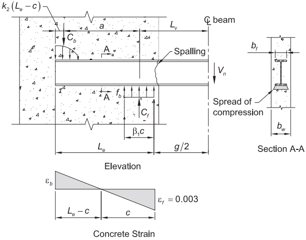
Figure description:
Analytical Model for Embedded Steel Beam in a Concrete Wall/Pier-End Connectioning Structure and Concrete Strain Distribution Diagram Description Table Mapping Variable Definition to Visualization Attributes Component Geometry Force Stress Values Annotation Text Type Position Subtitle Elevation Section AA and Concrete Strain Diagrams Additional Notes The figure depicts a double-curvature-like internal stress state with two opposing compression resultants (C_b and C_f balancing the external shear (V_n. The concrete strain is assumed to be linear, reaching a typical design maximum of 0.003 at the spalling face.
Mechanics of a Steel Beam Embedded in Concrete
Annotations
- Spalling (text_label - position: Concrete face at the bottom entry point of the beam)
- Spread of compression (text_label - position: Base of the compression zone in Section A-A)
- CL beam (text_label - position: Vertical dashed line representing the beam's centerline)
- Section A-A (text_label - position: Label for the cross-sectional view)
| Variable | Description | Diagram Context |
|---|---|---|
| L_e | Total embedded length of the steel beam | Elevation |
| g / 2 | Distance from the concrete face to the beam centerline | Elevation |
| L_v | Distance from beam centerline to the centroid of back compression force C_b | Elevation |
| a | Horizontal distance between the centroids of forces C_b and C_f | Elevation |
| c | Distance from the concrete face to the neutral axis | Elevation / Strain |
| L_e - c | Distance from the embedded end of the beam to the neutral axis | Elevation / Strain |
| beta_1 * c | Length of the rectangular stress block for force C_f | Elevation |
| k_2 * (L_e - c) | Centroid location of the back stress block from the beam end | Elevation |
| C_b | Resultant compression force at the top back of the embedded beam | Elevation |
| C_f | Resultant compression force at the bottom front of the embedded beam | Elevation |
| f_b | Bearing stress distribution on the beam | Elevation |
| V_n | Nominal shear force applied at the beam centerline | Elevation |
| epsilon_b | Maximum concrete compressive strain at the embedded end | Strain |
| epsilon_f | Maximum concrete compressive strain at the face (0.003) | Strain |
| b_f | Width of the steel beam flange | Section A-A |
| b_w | Width of the concrete wall | Section A-A |
Fig. C-H4.4. Method for computing the embedment capacity.
adequate tension development length above and below the flanges of the coupling beam, as shown in Figure C-H4.5. The vertical reinforcement in wall boundary elements, if present, is typically sufficient to meet these requirements.
Steel coupling beams may be encased sections, i.e., the coupling beam itself is encased in reinforced concrete. Previous research (Gong and Shahrooz, 2001a, 2001b) indicates that nominal encasement significantly improves resistance to flange and web buckling, which in turn enhances the shear strength and flexural strength of the coupling beam. The required embedment length must be computed recognizing the beneficial effects of encasement. Equations H4-6 and H4-6M for computing the shear strength of encased coupling beams are based on meeting the ACI 318 minimum shear reinforcement requirements. Hence, minimum shear reinforcement needs to be provided regardless of the calculated value of shear force in the coupling beam.