9.5.1 Shear Loaded Joint Example
This example calculation uses the joint defined in Figure 9-26.
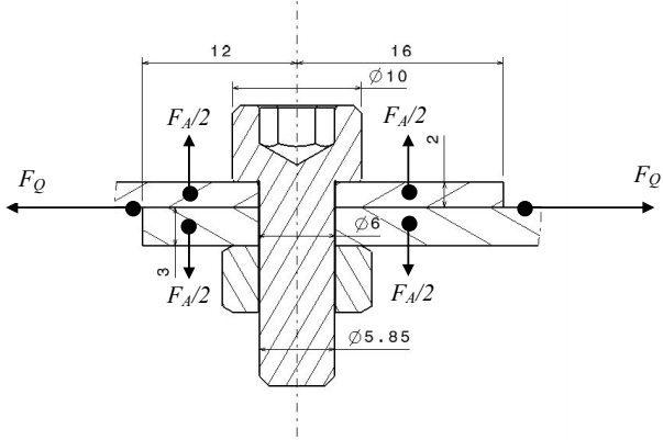
Figure description:
Entities:
- Bolt: Hexagonal head bolt with a shaft diameter of .
- Nut: Secured at the bottom of the bolt.
- Plates/Flanges: Two overlapping plates clamped together by the bolt and nut.
- Hole: Clearance hole through the plates with a diameter of .
Dimensions:
- Bolt Head Diameter:
- Bolt Shank Diameter:
- Hole Diameter:
- Top Plate Thickness: 2
- Bottom Plate Thickness: 3
- Horizontal Distance (Left: 12 from center line to edge.
- Horizontal Distance (Right: 16 from center line to edge.
Forces:
- : Shear loads acting horizontally in opposite directions on the plates.
- : Axial loads acting vertically outward from the interface on both sides of the bolt (total axial load .
Figure 9-26 - Shear loaded joint example
The friction coefficient at the interface between the flanges,
The strength of this structure is verified only by analysis. The safety factor for yield sf y , ultimate loads sf ult and slipping sfslip is read from Table 5-4. The value of sf y and sf ult is multiplied with the joint fitting factor 1 , 15.
sfy = 1,25 x 1,15 = 1,4375 sfult = 2 x 1,15 = 2,3 sfslip = 1,25 (non safety critical)
In addition to the axial load of Section 7.14, the joint is also subject to a shear load. Thus, the loads to which this joint is subjected are as follows:
FA = 1000 N FQ = 1000 N
The joint is first checked for its friction grip capacity. This is done by calculating the margin of safety on slipping using Equation [9.2.6]. There is only one interstice in this joint so x = 1.
The MoS for slipping is below zero, therefore it is important to re-analyse the joint as a bearing joint. Alternatively, if the joint has multiple fasteners, MoSslip can be recalculated with the average preload FV,av .
Therefore, the margins of safety on fastener shear loads are determined for yield and ultimate using the theory of Section 9.3.2. First, the fastener’s strength utilisation ratios are determined using equations[9.3.7] to [9.3.10],
Since the thread is in the shear plane of the joint, it is important to use equations [9.3.3] & [9.3.4] to calculate the combined stress utilisation ratios,
Thus, the MoS on fastener failure can be calculated using equations [9.3.13] and [9.3.14],
Next, it is important to check the strength of both flanges for hole bearing and shear-out. Both flanges consist of AA 7075 T7351.
For flange 1;
Thickness t1 = 2 mm Hole diameter Dh = 6,5 mm Edge distance ratio al /Dh = 16/6,5 = 2,46
That is above 2,0, so the bearing strength of the material is the value for the edge distance ratio of 2,0. The margins of safety on hole bearing is analysed for flange 1 are calculated using equations[9.3.23] and [9.3.24],
For flange 2; Thickness t2 = 3 mm Hole diameter Dh = 6,5 mm Edge distance ratio al /Dh = 12/6,5 = 1,85
The edge distance ratio is less than 2,0 so the bearing allowables can be found by linear interpolation between the value for and ,
Now, the margins of safety on hole bearing for flange 2 are,
Finally, the MoS for flange shear-out is calculated using equation [9.3.27],
For flange 1;
For flange 2;
9.5.2 Net Tension Section Failure Example
This example is based on the shear joint in Figure 9-27. The shear load is 50kN and the material ultimate stress is 427MPa.
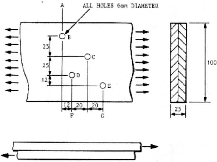
Figure description:
Holes and Labels:
- Holes: B, C, D, E
- Vertical Reference Lines: A, F, G
- Note: ALL HOLES 6mm DIAMETER
Dimensions (mm:
- Vertical spacing between B and C: 25
- Vertical spacing between C and D level: 25
- Vertical spacing between D and E level: 12
- Horizontal spacing between lines A and F: 12
- Horizontal spacing between lines F and C level: 20
- Horizontal spacing between C level and G: 20
- Total height of cross-section: 100
- Total width of cross-section: 25
Key Entities and Symbols:
- Plate under tensile load (indicated by arrows
- Top view, side cross-section, and bottom edge view of a lap joint
Inspection of the joint shows three potential fracture paths across the joint; ABDF, ABCDF and ABCEG.
The summed hole areas for each potential failure path across a flange are calculated using equation [9.3.20],
ABDF:
ABCDF:
ABCEG:
The largest value of Aholes is 141mm2 , which occurs for failure path ABDF.
The smallest net tension section is now calculated with equation [9.3.19],
The proportion of net section lost by holes is calculated with
The reduction factor for ultimate strength in the net tension section is now found using the graph in Figure 9-14. For the material type 1. Section 9.3.3.2 shows that the reduction factor KR is found to be approximately 0.9.
The margin of safety on net tension section failure can now be calculated using equation [9.3.21],
9.5.3 Eccentric Shear Bearing Joint Example
This example is taken from Reference 9.1. This example considers an eccentric shear load acting on the group of six symmetric fasteners shown in Figure 9-28.
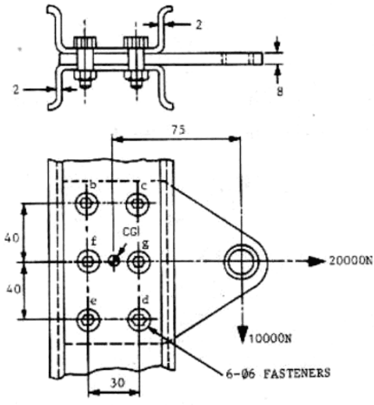
Figure description:
Entities:
- Fasteners: Group of 6, diameter Ø6, labeled b, c, d, e, f, g.
- Load Point: Point where external forces are applied.
- CG: Center of gravity of the fastener group.
Dimensions (in millimetres:
- Vertical fastener spacing: 40 mm (between rows, total 80 mm.
- Horizontal fastener spacing: 30 mm (between columns.
- Load offset: 75 mm from CG to the vertical load axis.
- Material thicknesses: 2 mm (outer members, 8 mm (central plate.
Applied Loads:
- Horizontal force: 20000 N.
- Vertical force: 10000 N.
ALL DIMENSIONS IN MILLIMETRES
Figure 9-28 - Offset Loads on Fastener Groups

Figure description:
Figure 9-29 Force components on fasteners
Key Entities:
- CG: Centroid of the fastener group.
- Fasteners: Six fasteners labeled b, c, d, e, f, and g.
Force Components:
- Vertical Components (: Each fastener has a downward vertical force vector (.
- Horizontal Components (:
- Fasteners on the left (b, g, e have horizontal vectors pointing to the left (.
- Fasteners on the right (c, f, d have horizontal vectors pointing to the right (.
The centroid of the group (marked ‘CG’ in Figure 9-28) is determined by symmetry. The fasteners all have the same bearing and shear areas, therefore, relatively simple calculations can be made to determine the shear loads on the fasteners,
Horizontal load on each fastener: Vertical load on each fastener:
Moment at CG:
Load due to moment on fasteners , , and with equation [9.4.4]:
Load due to moment on and with equation [9.4.4]:
The force components for each fastener are shown in Figure 9-29. For more complex fastener group geometry equation [9.4.3] is needed.
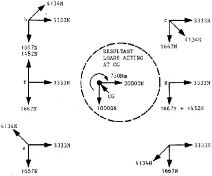
Figure description:
Central Entity: CG (Center of Gravity
- Resultant Loads:
- Horizontal force: 20000N (right
- Vertical force: 10000N (down
- Moment: 750Nm (clockwise
Fastener Locations and Loads:
- Fastener b:
- Horizontal: 3333N (right
- Vertical: 1667N (down
- Diagonal: 4134N (up-right
- Fastener c:
- Horizontal: 3333N (right
- Vertical: 1667N (down
- Diagonal: 4134N (down-right
- Fastener f:
- Horizontal: 3333N (right
- Vertical: 1667N (up, 1452N (up, 1667N (down
- Fastener g:
- Horizontal: 3333N (right
- Vertical: 1667N + 1452N (down
- Fastener e:
- Horizontal: 3333N (right
- Vertical: 1667N (down
- Diagonal: 4134N (up-left
- Fastener (bottom right, unlabeled:
- Horizontal: 3333N (right
- Vertical: 1667N (down
- Diagonal: 4134N (down-left
Figure 9-29 - Vector addition of the fastener loads
It can be seen by inspection that fastener c is the critical fastener, since all components of force act in the same quadrant (downwards to the right). Now that the most highly loaded fastener has been determined, it is important to determine the margins of safety for bearing joints according to Section 8.3.