7.6.1 Overview
The calculation of the compliance of the clamped parts, δ , is more complicated than that of the fastener c due to the 3-dimensional state of stress state in the joint that is induced by the preload. The method presented here (based on Reference 7.3) neglects the compliance of the interstices, and therefore it is most accurate for joints with a small number of clamped parts. If needed (e.g. when many plates are clamped together), the compliance of the clamped parts can be determined by experiment or finite element analysis.
The compliance of the camped parts is calculated by the integral,
where; A(z) is the cross-sectional area of the assumed compression zone within the clamped parts (explained in Sections 7.6.2 to 7.6.4), z is the distance through the clamped parts, Lc is the length of the clamped parts, and E c is the modulus of elasticity of the clamped parts.
When multiple materials are used in the clamped parts, it is important to use the more general form of Equation [7.6.1],

Figure description:
Key Information:
- Figure Title: Figure 7-10 - Compression zones in cylindrical clamped parts.
- Diagram Components: Three cross-sectional diagrams of clamped cylindrical parts showing hatched compression zones.
- Entities and Variables:
- : Inner diameter/hole diameter.
- : Under-head bearing diameter.
- : Available diameter of the flange.
- : Limiting diameter of the compression zone.
- : Total clamped length.
- : Angle of the compression cone.
- Left Diagram (Fully Developed: Shows compression spreading to a limiting diameter ( within wide flanges.
- Middle Diagram (Compression Sleeve: Shows a uniform cylindrical compression zone where the flange diameter ( is smaller than the bearing diameter (.
- Right Diagram (Limited Spreading: Shows a compression zone constrained by the outer edge of the flange (, where .
7.6.2 Compression Zone Configurations
7.6.2.1 Overview
The configuration of the compression zone depends on the geometry of the clamped parts. The following sections explain the possible configurations. Equations for calculating the compliance of the various configurations are given in Section 7.6.4.
7.6.2.2 Cylindrical Clamped Parts
Figure 7-10 shows the three possible compression zones (hatched) for cylindrical clamped parts. For clarity, the figure assumes that the flanges are compressed between infinitely stiff washers with under- head bearing diameter Duh,brg . When the flanges are wider than the under-head bearing diameter, the compression zone spreads out. For the theory presented here, it is assumed that the compression zone spreads within a conical surface. In many cases the compliance of the washers is also significant. If so, it is important that are also treated as clamped parts.
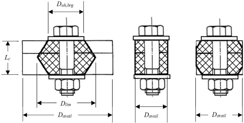
Figure description:
The image illustrates three configurations of compression zones in cylindrical clamped parts:
- Entities:
- Bolted assemblies: Each includes a bolt, a nut, and two washers clamping two cylindrical parts.
- Compression zones: Indicated by cross-hatched regions within the clamped parts.
- Dimensions and Variables:
- : Under-head bearing diameter, shown at the top washer interface.
- : Total length of the clamped parts.
- : Limiting diameter of the compression zone (left configuration.
- : Available external diameter of the clamped parts.
- Configurations (Left to Right:
- Fully Developed Zone: Compression zone spreads out into two cones reaching a maximum width ( where is much larger than the zone.
- Compression Sleeve: Compression zone is a uniform cylinder because is equal to or smaller than .
- Restricted Zone: Compression zone begins to spread conically but is truncated by the outer diameter of the parts (.
Figure 7-10 - Compression zones in cylindrical clamped parts
7.6.2.3 Fully Developed Compression Zone
The configuration on the left of Figure 7-10 has flanges that are sufficiently wide to allow full spreading of the compression zone to the limiting diameter, Dlim . In reality, the shape of the 3-dimensional zone of compression in an isotropic material is a paraboloid. However, the method approximates the compression zone as a pair of compression cones. The two cones are symmetric about the mid-point of the clamped parts length, Lc , (which does not necessarily correspond to the interstice between the flanges).
7.6.2.4 Compression Sleeve
The middle configuration of Figure 7-10 has narrow flanges that fit entirely within the underhead bearing diameter, i.e. Davail < Duh,brg . In this case, the compression zone is a ‘sleeve’ (a uniform compression cylinder).

Figure description:
- Text: "E CSS"
- Shape: A parallelogram with a blue outline.
- Layout: The letter "E" is on a white background section, and the letters "CSS" are on a dark blue background section.
- Font: Italicized serif.
- Colors: Dark blue and white.
7.6.2.5 Partially Developed Compression Zone
The configuration to the right of Figure 7-10 has flanges of intermediate edge clearances so a partial length sleeve of diameter Davail approximates the compression zone, and two deformation cones are formed above and below the sleeve.
7.6.2.6 General Case of Non-Cylindrical Clamped Parts
In the general case with clamped parts that are not axially symmetric about the fastener’s axis multiple edge distances are present (see Figure 7-11). For this type of joint, it is important to determine the configuration of the deformation zone by the minimum edge distance according to,
Equation [7.6.3] results in a value of clamped parts compliance that is higher than reality, which can introduce significant (non-conservative) inaccuracies in the MoS. Section 7.6.2.9 discusses this issue in more detail.
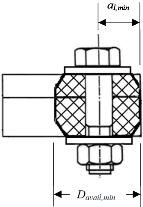
Figure description:
- Entities:
- Hex head bolt and nut assembly.
- Two flat washers.
- Two clamped plates.
- Cross-hatched compression zone (deformation zone.
- Dimensions/Variables:
- : Minimum edge distance from the bolt centerline to the edge of the clamped part.
- : Minimum available diameter of the compression zone.
- Visual Details:
- The compression zone is represented by a cross-hatched area shaped like two truncated cones meeting at the interface of the two plates.
- The compression zone is truncated on the right side by the edge of the material.
- The material on the left side extends further than the material on the right.
Figure 7-11 - The compression zone when multiple edge distances are present
7.6.2.7 The Compression Zone in Threaded Hole Joints
Unlike nut-tightened joints, threaded hole joints develop only one compression cone. This cone develops fully if the flange has an available diameter large enough to allow the cone to extend to the interstice of the threaded hole flange (see left of Figure 7-12).
When the compressed flange has insufficient diameter, the compression cone stops at the flange edge and a compression sleeve forms between the base of the compression cone and the interstice of the insert flange (see right of Figure 7-12).
The threaded hole flange does not contribute to the clamped parts compliance, although it is important to include in the calculation of the fastener compliance according to Table 7-1.
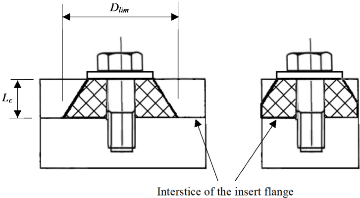
Figure description:
- : Dimension indicating the total width of the compression zone across the fastener.
- : Dimension indicating the height of the top material layer.
- Interstice of the insert flange: Label pointing to the horizontal interface between two material layers.
- Fasteners: Two bolt and washer assemblies are shown, each securing a top layer to a bottom substrate.
- Compression zone: Indicated by cross-hatched trapezoidal areas surrounding the fasteners within the top material layer.
Figure 7-12- Approximation of the Compression Zone for Insert Joints
7.6.2.8 Interfering Compression Zones
When a joint has multiple fasteners, the available diameter of the deformation zone around each fastener is affected by the interference effect with its neighbour/s (see Figure 7-13). The result of this interference is a decreased compliance, relative to a similar joint without overlapping compression zones. This leads to a conservative estimate of the fasteners tensile loading, but a non-conservative estimate of the flange compression (see Section 7.6.2.9 below).
When calculating margins of safety that depend on flange compression (e.g. gapping, and slipping), it is conservative to neglect the overlapping compression zones when calculating the compliance of the clamped parts.
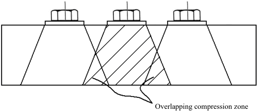
Figure description:
The image shows a diagram with the following key information:
- Entities:
- Three Fastener Assemblies: Each consisting of a bolt head/nut and a washer resting on a flat surface.
- Substrate/Flange: A rectangular block representing the clamped material.
- Compression Zones: Indicated by trapezoidal outlines extending downwards from each washer through the material.
- Hatched Region: The central compression zone is filled with diagonal hatching.
- Key Detail:
- Overlapping Compression Zone: Pointed out by two leader lines indicating the areas where the trapezoidal compression zones of adjacent fasteners intersect within the material.
Figure 7-13 - The compression zone with multiple interacting fasteners

Figure description:
- Text: E CSS
- Visual details: Stylized, italicized white font on a blue parallelogram-shaped background.
- Key entity: ECSS logo.
7.6.2.9 Influence of the Clamped Parts Compliance
Since the methods presented in this section for calculating the compliance of the clamped parts are subject to some approximations, it is worthwhile examining the effects of overestimating and underestimating this compliance.
Referring to Equation [7.4.6], overestimating the clamped parts compliance gives rise to an artificially high force ratio, Φ . This leads to an overestimate of the force increment experienced by the fastener, which is therefore conservative for the calculation of fastener tensile failure modes such as fastener shank failure or thread pull-out. However, it also leads to an underestimate for force the increment experienced by the clamped parts, which gives non-conservative for the flange performances related to separation, sealing, friction grip, crushing, etc.
In the opposite case of the clamped parts compliance being underestimated, the force ratio is artificially low. This leads to non-conservative values for the fastener and thread strengths.
Accordingly, it is recommended that more detailed analysis or testing is undertaken in cases where the clamped parts compliance might be a critical factor in the justification of the joint’s design.
7.6.3 Determining the Compression Zone Configuration
7.6.3.1 Overview
It is important to determine the appropriate configuration of the compression zone for each fastener in the joint. The following sections present the equations necessary to determine which compression zone configuration is applicable.
7.6.3.2 Diameter of the Compression Zone
First, the edge distance of the flanges, a l, is used to calculate the available diameter for the compression zone,
Then, this is compared with the limit diameter of the compression cone as given by,
where; Duh,brg is the fastener’s under-head bearing diameter, Lc is the compression length, and φ is the compression cone half angle (see Section 7.6.3.3 below), and w=1 for a nut-tightened joint and w=2 for a threaded hole joint.
7.6.3.3 The Compression Cone Half Angle
The compression cone’s half angle, φ , depends strongly on the available area of the flanges. It is also influenced by the fastener’s under-head diameter, the hole diameter and the distribution of the compression load. Reference 7.2 proves empirically derived equations for calculating φ .
For nut-tightened joints is given by,
and for insert joints it is given by,
where the following non-dimensional parameters are used,
7.6.3.4 Existence of a Cone and Sleeve
The existence of the sleeve is determined as follows:
If , the compression zone is fully developed into a cone (or pair of cones for nut-tightened joints)
If , no compression cone develops and only a sleeve has to be used for calculation purposes
If , that compression zone is formed by a partial compression sleeve and compression cone/s
The above cases, 1 to 3, correspond to the left, middle and right configurations of Figure 7-10.
7.6.4 The Compression Zone Compliance
The compliance of the clamped parts, , for the case of fully developed compression cone/s (i.e. with ) is given by,
where is the modulus of elasticity of the clamped parts.
For partially developed compression cone/s (i.e. ), the clamped parts compliance is given by,
Equation [7.6.11] includes the effect of both the compression cone/s and sleeves, and is appropriate when the clamped parts have the same modulus of elasticity.
If the compliances of the cone and sleeve are calculated separately (for example when multiple materials are present in the clamped parts), it is important to calculate the clamped parts compliance by,
where the cone's compliance is,
and the sleeve's compliance is,
and the lengths of the cone and sleeve are given by,
and,
For the case where only a compression sleeve exists (Duh,brg < Davail ), Equation [7.6.16] is used for the sleeve compliance and Lsleeve is equal to the combined length of the clamped parts, Lc ., and w=1 for a nut- tightened joint or w=2 for a threaded hole joint.
7.6.5 Gasket Compliance
If the clamped parts include a gasket, it is possible to estimate the total compliance of all clamped parts using,
where δ is the compliance of the elastic clamped parts (flanges, washers, etc) and e δ g is the compliance of the gasket.
However, in general, the load-displacement characteristics of gaskets are non-linear (as shown in Figure 7-14) and the compliance of the gasket is much greater than that of the other clamped parts. Therefore, deformation of the gasket often dominates the elastic behaviour of the joint. Not only does δ g vary with the applied load, but in addition the gasket behaviour is often partially plastic (see Figure 7-15), leading to a hysteresis effect. If the load is dynamic, the hysteresis can disappear over a period of time, and therefore it is important to analyse gasket joints differently depending on whether they are intended for static or dynamic service.

Figure description:
- Text: E CSS
- Visual elements: The letter "E" is in blue and italicized, set against a white background. The letters "CSS" are in white, set against a dark blue background. Both segments are contained within a single dark blue-bordered parallelogram.
- Key entity: ECSS logo.
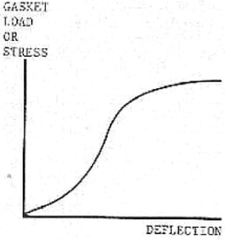
Figure description:
Gasket Load or Stress vs. Deflection Chart
Gasket Load or Stress vs. Deflection
| Deflection (Relative Scale) | Gasket Load or Stress (Relative Scale) |
|---|---|
| 0.0 | 0.0 |
| 1.0 | 0.2 |
| 2.0 | 0.6 |
| 3.0 | 1.5 |
| 4.0 | 3.5 |
| 5.0 | 6.5 |
| 6.0 | 8.5 |
| 7.0 | 9.4 |
| 8.0 | 9.8 |
| 9.0 | 10.0 |
| 10.0 | 10.1 |
Notes: The data points in the table are estimated relative values based on the visual curve in the image, as no numerical axis scales were provided. The graph depicts a characteristic S-curve (sigmoid relationship between gasket deflection and the resulting load or stress.)
Figure 7-14 - Typical Gasket Deflection
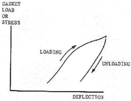
Figure description:
GASKET LOAD OR STRESS vs DEFLECTION
Loading and Unloading Curves
Annotations
- LOADING (text_label - position: Above the top curve)
- UNLOADING (text_label - position: Below the bottom curve)
- Loading direction arrow (arrow - position: Points up and right along the top curve)
- Unloading direction arrow (arrow - position: Points down and left along the bottom curve)
| DEFLECTION (Relative) | LOADING (GASKET LOAD OR STRESS, Relative) | UNLOADING (GASKET LOAD OR STRESS, Relative) |
|---|---|---|
| 0.40 | 0.40 | null |
| 0.50 | 0.60 | null |
| 0.65 | 0.80 | null |
| 0.85 | 0.95 | 0.95 |
| 0.80 | null | 0.75 |
| 0.75 | null | 0.50 |
Notes: The chart illustrates the hysteresis behavior of a gasket. The loading path shows stress increasing with deflection, while the unloading path follows a different curve as stress is released. Since no numerical scale is provided on the axes, relative values have been estimated to represent the visual shape of the curves.
Figure 7-15 – Gasket Showing Hysteresis
The coefficient of thermal expansion of a gasket can be different from that of the other clamped parts or the fastener hence temperature changes can affect joint performance.
Including an elastic-plastic nonlinear spring applied in the joint diagram results in a joint non-linear joint diagram such as shown in Figure 7-16. In this figure the amount of creep is indicated by the difference between the dotted and full lines.
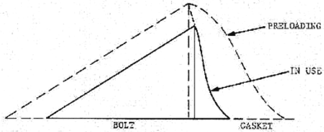
Figure description:
Bolt and Gasket Load Diagram
Load Distribution Characteristics
Legend
- PRELOADING — symbol: Dashed line
- IN USE — symbol: Solid line
Annotations
- BOLT (text_label - position: below left section of x-axis)
- GASKET (text_label - position: below right section of x-axis)
- Preloading Peak Line (vertical_line - position: x = 58)
- In Use Peak Line (vertical_line - position: x = 62)
| State | X (Relative Units) | Y (Relative Load) |
|---|---|---|
| PRELOADING (Dashed) | 0 | 0 |
| PRELOADING (Dashed) | 58 | 100 |
| PRELOADING (Dashed) | 90 | 0 |
| IN USE (Solid) | 12 | 0 |
| IN USE (Solid) | 62 | 85 |
| IN USE (Solid) | 78 | 0 |
Notes: The diagram represents a joint stiffness or Rötscher diagram, showing the load characteristics of a bolt and a gasket. The dashed line represents the initial preloading condition, and the solid line represents the condition when the assembly is 'in use'. The 'BOLT' region shows a linear load-displacement relationship, while the 'GASKET' region shows a curved relationship.
Figure 7-16- Joint Diagram for a Gasket Joint Showing Gasket Creep
The difficulties in predicting gasket creep and spring rates has led to an empirical approach, which uses experimentally derived gasket factors, y and m for each type of gasket material:
- • The y factor gives the initial gasket stress which can be converted to a minimum interface clamping load, FK,req , assuming uniform gasket loading. A typical value for a soft aluminium gasket is 60 N/mm² and silicon rubber 3 N/mm².
- • The m factor is a shape factor experimentally derived for each gasket type. It is the ratio of gasket pressure to contained pressure for an effective seal. Typical values for soft aluminium and silicon rubber are 3,25 and 1,..25 respectively.
Section 6.4.5 contains some recommendations for designing joints in order to minimise unwanted compliance effects due to gaskets.