6.4.1 Overview
There are five mechanisms that cause relaxation preload loss in bolted joints:
- a. Embedding
- b. Fastener Group Interactions
- c. Gasket Creep
- d. Metallic Creep
- e. Tensional Relaxation
It is important that the user is aware of the possibilities of such preload reductions and estimations of their magnitude are considered in the design calculations. It is also important to note that vibration loosening, which can cause relaxation, is outside of the scope of this section and stress relaxation, usually due to a combination of stress and high temperature, is not applicable.
Creep is a significant factor when the temperature exceeds approximately 50% of the recrystallisation temperature of the respective material.
In addition to the five mechanisms listed above, preload loss can also occur due to localised plastic deformations in the fastener, if it is subjected to repeated loadings above material yield. This effect is further explained in Section 7.13.
6.4.2 Embedding
6.4.2.1 Overview
When new fasteners are first tightened, see Figure 6-3, the male and female threads, the under-head and under-nut surfaces and the clamped parts interfaces contact each other only on microscopically small high spots, where the surface "asperities" touch, as illustrated in Figure 6-4. The material at these high spots is overloaded, well past their yield point, during initial tightening and subsequently creeps until a large enough area of the available contact surface has been engaged to stabilize the process.
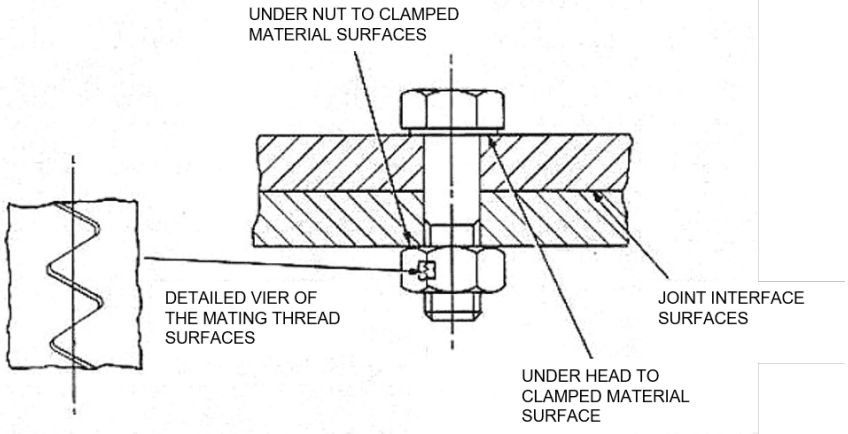
Figure description:
Key Entities:
- Fastener assembly: Comprised of a bolt and a nut.
- Clamped material: Two plates held together by the fastener.
- Threads: Male and female mating surfaces.
Key Information (Contact Surfaces:
- Under nut to clamped material surfaces: The interface between the base of the nut and the bottom plate.
- Joint interface surfaces: The contact area between the two clamped material plates.
- Under head to clamped material surface: The interface between the underside of the bolt head and the top plate.
- Mating thread surfaces: Shown in a "Detailed Vier [View" callout, illustrating the contact between the bolt and nut threads.
Figure 6-3 - Fastener Faying Surfaces
Figure description:
- Entity: ECSS
- Literal Text: E CSS
- Visual Description: A purple, slanted rectangular box (parallelogram containing white, italicized capital letters.
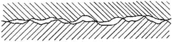
Figure description:
Image Content:
- Top Entity: A solid material section represented by diagonal hatching lines sloping downward from left to right.
- Bottom Entity: A solid material section represented by diagonal hatching lines sloping upward from left to right.
- Interface: A wavy, irregular horizontal boundary where the two materials meet.
- Key Detail: The interface shows localized points of contact interspersed with microscopic gaps or voids between the irregular surface peaks (asperities of the two materials.
Figure 6-4 - Microscopic View of Surface Asperities Initially in Contact
In addition, plastic flow often occurs at the highest stressed points such as in thread roots, at the first engaged thread in the nut, or at other stress concentrations caused by imperfect manufacture (e.g. errors in squareness, flatness, concentricity, etc.).
These relatively short-term relaxation effects are known as "embedding". After tightening the rate of relaxation is a maximum, reducing exponentially, usually over the first minutes, to a constant very low rate of creep as illustrated in Figure 6-5. Typically embedding accounts for only a few percent loss of initial preload, however 5 to 10% preload loss is not uncommon, and maximums of 25% for torque tightening and 40% for hydraulic tensioning have been recorded.
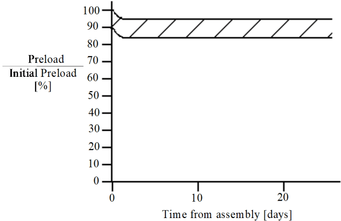
Figure description:
Preload / Initial Preload [% vs. Time from assembly [days
Annotations
- Preload variation range (shaded_area - position: Shaded region between the upper and lower boundary curves)
| Time from assembly [days | Upper Boundary of Preload / Initial Preload [% | Lower Boundary of Preload / Initial Preload [% |
|---|---|---|
| 0 | 100 | 90 |
| 0.5 | 98 | 88 |
| 1 | 96 | 86 |
| 2 | 95 | 84 |
| 5 | 95 | 84 |
| 10 | 95 | 84 |
| 15 | 95 | 84 |
| 20 | 95 | 84 |
| 25 | 95 | 84 |
Notes: The chart illustrates the loss of preload over time, which stabilizes after an initial rapid decrease within approximately the first two days. The area between the two curves is hatched, representing the expected variation range of the preload percentage.
Figure 6-5 - Embedding Preload Decay
The preload loss to be put in Equation [6.3.15] depends on the plastic deformation of the joint caused by embedding. The following relationships apply,
where; fb,V is the elongation of the fastener due to the preload and fc,V is the elongation of the flanges under preload, and δ and b δ are the compliances of the fasteners and the clamped parts respectively c (see Sections 7.4 and 7.7).
Thus it follows that,
The value of f Z depends on the surface roughness, the number of interstices in the joint and the material type. For example, using aluminium for the female thread can double the value of fZ compared with that of steel.
For uncritical cases a value of 5% of the preload can be used for calculation purposes, i.e.:
Otherwise it is important that the appropriate preload loss is determined by experiment. If no experimental data can be gained, Table 6-3 can be used to find approximate values. This table can only be used if the temperatures are below 50% of the recrystallisation temperatures.
| Average Surface Roughness, Rz (as per Ref. 7.3) | Type of External Load Applied to Joint | Standard Values for Embedding [µm] | ||
|---|---|---|---|---|
| In the thread | Per under- head or under-nut interface | Per inter- flange interstice | ||
| < 10 µm | Axial | 3 | 2,5 | 1,5 |
| Shear | 3 | 3 | 2 | |
| 10 µm < x < 40 µm | Axial | 3 | 3 | 2 |
| Shear | 3 | 4,5 | 2,5 | |
| 40 µm < x < 160 µm | Axial | 3 | 4 | 3 |
| Shear | 3 | 6,5 | 3,5 | |
6.4.2.2 Tightening Methods
The asperities of surfaces subjected to frictional sliding during assembly, such as during conventional torque tightening, tend to shear and flatten thereby producing more embedding during assembly and leaving less to take place after tightening. In cases where embedding becomes critical (e.g. galling due to excessive friction resulting in localized welding), it is recommended to consider tightening methods that do not induce frictional sliding (e.g. hydraulic tensioning).
6.4.2.3 Retightening
The magnitude of embedding preload loss can be greatly reduced in critical cases by torque tightening, loosening and retightening several times. However, it is important to give attention to the reduction of self-locking torque due to multiple tightening cycles (see Section 12.7.3).
6.4.2.4 Hard Clamped Material
It is also an advantage, where possible, to use flanges made from harder materials or washers that resist embedding.
6.4.2.5 Controlled Thread Dimensions
To minimise preload loss in the thread, it is important to use bolts with the tightest tolerance class of thread that is available. For example Class 3 is preferred to Class 2 as are root radius controlled "J" class threads to standard threads, and it is important to use rolled threads in preference to cut threads. The use of fasteners with cut machined threads is normally subject to approval.
6.4.2.6 Conical Components
It is important to avoid conical joint mating surfaces as illustrated in Figure 6-6. For these joint configurations relaxation perpendicular to the conical surface (due to embedding) results is a far greater relaxation in the direction of the fastener axis.
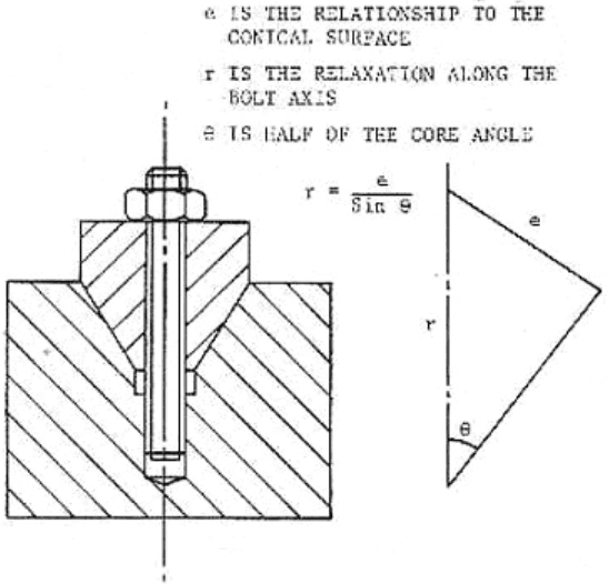
Figure description:
The image illustrates the relationship between surface relaxation and axial relaxation in a joint with conical mating surfaces.
Key Entities:
- Bolt and Nut: Fastening components securing two hatched cross-section parts.
- Conical Mating Surface: The angled interface between the two clamped components.
- Geometric Diagram: A right-angled triangle representing the vector relationship between the defined variables.
Visible Text and Formula:
- e: The relationship to the conical surface.
- r: The relaxation along the bolt axis.
- θ: Half of the cone angle.
- Formula:
Figure 6-6 - Joint with Conical Mating Surfaces
6.4.2.7 Component Stiffness
It is important that long thin compliant fasteners are used in preference to short, stubby stiff fasteners. The total amount of embedding is the same for both for a given preload but for the compliant fastener the stiffness is less and hence a smaller preload loss occurs (see Figure 6-7). Similarly Belleville washers (conical spring washers as shown in Figure 6-8) can be used to increase the compliance of the clamped parts and hence reduce the effect of embedding.
Figure description:
The image contains the stylized text "ECSS" inside a parallelogram with a blue background. The "E" is italicized and appears on a white background within the left side of the parallelogram, while "CSS" is on the blue background.
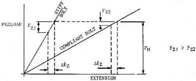
Figure description:
Bolt Stiffness Comparison Chart - Preload vs Extension for Stiff and Compliant Bolts
PRELOAD vs EXTENSION
Legend
- STIFF BOLT — color: null; symbol: Solid line
- COMPLIANT BOLT — color: null; symbol: Solid line
Annotations
- F_Z1 (vertical_dimension - position: Vertical change for STIFF BOLT)
- F_Z2 (vertical_dimension - position: Vertical change for COMPLIANT BOLT)
- \Delta\ell_Z (horizontal_dimension - position: Horizontal extension increment)
- F_M (reference_line - position: Top horizontal dashed line representing target preload)
- F_Z1 > F_Z2 (text_label - position: Right side of plot)
| Extension | Preload (STIFF BOLT) | Preload (COMPLIANT BOLT) |
|---|---|---|
| 0 | 0 | 0 |
| \ell_1 | F_M - F_{Z1} | null |
| \ell_1 + \Delta\ell_Z | F_M | null |
| \ell_2 | null | F_M - F_{Z2} |
| \ell_2 + \Delta\ell_Z | null | F_M |
Figure 6-7 - Effect of Fastener Stiffness on Preload Loss Due to Embedding
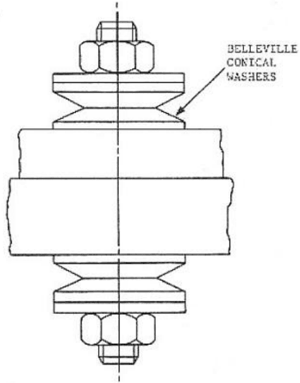
Figure description:
- Entities:
- Hexagonal nuts (2
- Threaded bolt/fastener with a central vertical axis
- Flat washers (2
- Belleville conical washers (4, arranged in two sets of opposing pairs
- Joined material plates (2
- Label: "BELLEVILLE CONICAL WASHERS" with a leader line pointing to the upper set of conical washers.
- Configuration: A bolt passing through two plates of material, secured with a nut, flat washer, and a pair of Belleville conical washers on each side.
Figure 6-8 - Increasing Joint Compliance Using Belleville Washers
6.4.2.8 Bearing Strength
Relaxation occurs by major material plastic flow if the bearing surfaces are not large enough or the applied stresses are not distributed properly.
It is important to ensure in the design, manufacture and quality control checking that:
- • The under head radius does not foul the edge of the clamped parts chamfer, which can result in a very small contact area leading to exaggerated embedding with a corresponding preload loss.
- • Conversely, the chamfer is not so great that too small an under head bearing area results and the bolt head embeds into the clamped material.
- • Slotted holes, which can greatly reduce the bearing area under the head or nut, are avoided.
6.4.2.9 Thread Engagement
The minimum acceptable thread engagement of high strength steel or titanium fastener is 0,8 times the nominal diameter of the fastener. It is important to use at least 1,5d thread engagement for such fastener used in aluminium tapped holes, even if wire thread inserts (e.g. helicoils) are used.
6.4.2.10 Lubrication Migration
Some lubricants can gradually migrate from the fastener and joint contacting surfaces causing a small amount of relaxation preload loss.
6.4.2.11 Surface Roughness
From the initial discussion of this section it is evident that if surface roughness is minimised by grinding or polishing the relaxation effects of embedding can be reduced, but not eliminated.
Another obvious point is that the total amount of embedding is related to the number of joint interfaces.
6.4.3 Fastener Group Interaction
6.4.3.1 Overview
Some short-term relaxation problems evolve due to interactions between fasteners in groups.
6.4.3.2 Elastic Interaction
When the first fastener in a group is tightened, it is elongated and the joint in its vicinity is compressed. When an adjacent fastener is tightened, the joint in the vicinity of the first fastener can be further compressed causing relaxation of that fastener. The amount of interaction depends on such factors as clamped parts stiffness, the spacing of fasteners and whether a gasket is used. Preload losses in the order of 50% to 100% have been recorded (see Reference 6.3). An example of this problem is given in Figure 6-9 and Figure 6-10 in which eight fasteners on the same flange are tightened in sequence. Figure 6-9 shows the "saw-tooth" effect of one tightening pass as the last fastener tightened in a particular quadrant end up with a greater preload than those immediately adjacent to it. However, after four passes Figure 6-10 illustrates that the final relaxation pattern is not a regular saw tooth. At each pass the joint is tightened by successively higher, but uniform, torques to the fasteners.
This problem can be partly overcome by giving higher initial preloads to those fasteners expected to relax the most, thus producing a more uniform fastener load after relaxation. The highest accuracy is achieved by monitoring preload tests, using a technique such as ultrasonic, and applying small amounts of extra torque to the fasteners with insufficient preload.
6.4.3.3 Bent Flanges
If flanges are soft, warped or bent, tightening one fastener can cause relaxation (or additional stress) in other fasteners. A precautionary final torque pass is always made when assembling joints with multiple fasteners.
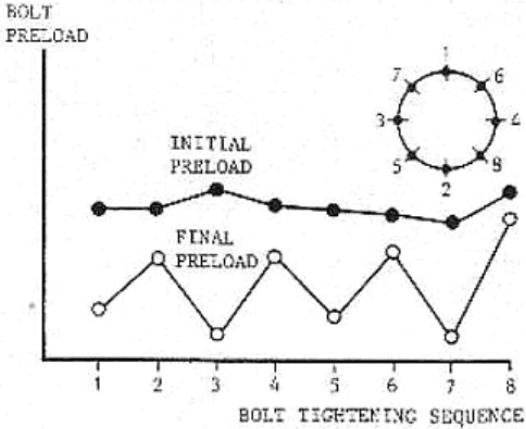
Figure description:
Bolt Preload
Bolt Preload versus Tightening Sequence
Legend
- INITIAL PRELOAD — color: black; symbol: solid line with black circles
- FINAL PRELOAD — color: black; symbol: solid line with open circles
| Bolt Tightening Sequence | Initial Preload | Final Preload |
|---|---|---|
| 1 | 4.8 | 2.5 |
| 2 | 4.8 | 4.0 |
| 3 | 5.5 | 1.5 |
| 4 | 5.0 | 4.0 |
| 5 | 4.8 | 2.0 |
| 6 | 4.5 | 4.2 |
| 7 | 4.2 | 1.5 |
| 8 | 5.5 | 4.0 |
Notes: The chart shows the relationship between the bolt tightening sequence and the preload for eight bolts. The y-axis, labeled 'BOLT PRELOAD', lacks a numerical scale, so values are estimated based on relative positions. A diagram in the upper right corner illustrates the circular bolt pattern numbered 1 through 8.
Figure 6-9 - Initial and Final Preload of a Typical Flange Joint for the First Tightening Pass.
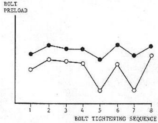
Figure description:
Bolt Preload Analysis Chart
BOLT PRELOAD vs BOLT TIGHTENING SEQUENCE
Legend
- Solid dots series — color: black; symbol: Solid circles connected by a line
- Hollow circles series — color: black; symbol: Hollow circles connected by a line
| BOLT TIGHTENING SEQUENCE | BOLT PRELOAD (Solid dots) | BOLT PRELOAD (Hollow circles) |\n| :--- | :--- | :--- |\n| 1 | 4.5 | 3.5 |\n| 2 | 5.6 | 4.6 |\n| 3 | 5.2 | 4.4 |\n| 4 | 5.2 | 4.2 |\n| 5 | 4.2 | 2.1 |\n| 6 | 5.6 | 4.1 |\n| 7 | 4.5 | 2.1 |\n| 8 | 5.3 | 4.4 |
Notes: The Y-axis (Bolt Preload does not have a numerical scale; the values provided in the table are estimated relative heights from the provided image. Significant drops in preload for the hollow circle series are observed at sequences 5 and 7.)
Figure 6-10 - Initial and Final Preload Levels after Four Tightening Passes.
6.4.3.4 Motorized Tightening Speed and Interaction Effects
If flanges with a large number of fasteners are tightened simultaneously using a motorized technique there is a great danger of high preload loss due to embedding. A fastener tightened alone can see higher stress than if tightened in a group, where all the bolts share the load evenly as it develops. Also this tightening process is usually carried out at relatively high speeds. It is therefore recommended that the torque is applied in a series of increments and that time is allowed between each pass for embedding to take place. This recommendation is particularly relevant where gaskets are used.
6.4.4 Gaskets
Outgassing constraints restrict the selection of gasket materials that are suitable for space applications. It is usually preferred, where possible, to eliminate gaskets and rely on metal-to-metal sealing of flanges. Where this cannot be achieved a preformed gasket from fully cured silicone rubber or a soft metal such as lead or a soft aluminium alloy is used to form the seal.
Gasket creep is another form of relatively short-term relaxation. Having a gasket in a joint ensures large amounts of relaxation compared to that expected with normal embedding. In fact, a gasket is deliberately designed to deform plastically to some extent in order to plug the paths through which the contained fluid or gas otherwise escape. Like any plastic material it can creep when first subjected to high surface pressures. The amount of creep is difficult to predict since it is dependent on many factors including the level of compressive load generated by the fasteners.
The following recommendations are given for design gasket joints:
- • To obtain the most uniform pull down, tighten flange bolts in a cross star pattern or, if the cost is justified, tighten several bolts simultaneously.
- • Use the most accurate method of tightening available.
- • Use the highest design aim preload possible without damaging the gasket or joint member.
- • If designing pressure vessels or pipe connections follow the relevant design codes of practices such as ASME VIII division 1 and BS 5500.
The non-linear characteristics of gaskets can significantly influence the clamped parts compliance. Section 7.6.5 contains an explanation of the compliance calculations for joints with gaskets.
6.4.5 Metallic Creep
Very high temperatures, which can cause relaxation due to a reduction of material strength, do not normally occur in space applications. However, differential thermal expansion can directly give preload loss and can also cause relaxation due to over stressing. Such thermo-elastic effects are discussed in Section 6.3.5.
6.4.6 Washers
Washers are used for a variety of reasons. Plain washers are used to spread the load into the clamped parts, to allow the use of oversized holes (making sure to use thick washers to avoid excessive bending), to prevent the fastener head or nut damaging the surface of the clamped parts, or to give controlled surface conditions at the under-head or under-nut interfaces. Many other types of special purpose washers exist such as insulating washers for thermal or electrical reasons, conical spring washers to minimise the effect of embedding, the dimpled or two piece crushable washers for preload detection, the straingauged face washer for use as a miniature load cell, shakeproof washers to prevent rotary loosening and toothed shear washers for slip prevention, etc. It is important to consider the compliance and relaxation properties of the particular washer type.
It is important that the analysis of clamped parts compliance (Section 7.7) takes into account compliance of the washers. Generally, the washer compliance can be calculated assuming that it behaves like a flange. If the washer is soft, the analysis can be done using the non-linear theory for gaskets (see Section 7.6.5).
Whenever washers are used, embedding (Section 6.4.2) is increased since there is at least one more interstice region with crushable surface asperities. For this reason, it is recommended to use hard washers whenever possible to minimise the embedding losses.
6.4.7 Torsional Relaxation
During the torque tightening process torsional stress is developed in the fastener in addition to the axial stress, which is necessary for the preload. The torsional stress is subject to varying amounts of relaxation, and it is generally believed to be the first stress to be relieved by relaxation. In most instances it disappears immediately when the wrench is removed. Also, it has been shown that the relaxation of torsional stress can induce extra tensile stress (see Reference 6.4). This self-tightening phenomenon, illustrated in Figure 6-11 is invariably masked by the greater axial embedding relaxation (see Reference 6.3). The amount of torsional stress primarily depends on the magnitude of the thread friction torque and the amount of relaxation. Whether relaxation is by head rotation or self-tightening depends largely on the under head friction conditions compared with those of the thread friction conditions.
Note that, despite this handbook recommends to consider total relaxation of the shear stress induced during installation, in special cases (i.e. large torque and high friction coefficients) a remaining torsional stress (typical value 50 %) needs to be considered.
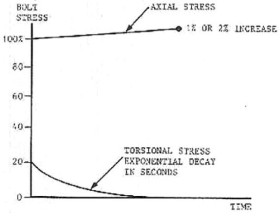
Figure description:
Axial and Torsional Bolt Stress Components
BOLT STRESS vs TIME
Annotations
- AXIAL STRESS (text_label - position: Upper line starting at y = 100%)
- 1% OR 2% INCREASE (text_label - position: Right end of AXIAL STRESS line)
- TORSIONAL STRESS EXPONENTIAL DECAY IN SECONDS (text_label - position: Lower curve starting at y = 20%)
| Time | Axial Stress (%) | Torsional Stress (%) |
|---|---|---|
| 0 | 100 | 20 |
| 1 | 100.3 | 12.1 |
| 2 | 100.6 | 7.4 |
| 3 | 100.9 | 4.5 |
| 4 | 101.2 | 2.7 |
| 5 | 101.5 | 1.6 |
| 6 | 101.8 | 1.0 |
Notes: The graph illustrates the behavior of bolt stress over time. Axial stress starts at 100% and increases linearly by approximately 1-2%. Torsional stress starts at 20% and undergoes exponential decay towards zero over a period of seconds.
Figure 6-11 - Self Tightening by Torsional Relaxation