5.3.1 Overview
The calculation of a mechanically fastened joint begins with the definition of the external operational loading environment, which includes the axial load FA , the shear load FQ , the bending moment MB and the torsional moment MT (if present). For the fastener analysis it is assumed, that these external forces and moments are known. Figure 5-4 shows a joint with the dimensions indicated.
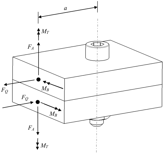
Figure description:
The image is a technical diagram of a mechanically fastened joint showing various forces and moments.
Key Entities and Details:
- Joint Assembly: Comprised of two rectangular blocks joined by a single socket-head bolt and nut.
- Dimensional Label:
- a: Horizontal distance from the bolt centerline to the application point of external loads.
- Forces:
- : Axial forces acting vertically in opposite directions.
- : Shear forces acting horizontally in opposite directions along the interface.
- Moments:
- : Torsional moments acting around the vertical axis of load application.
- : Bending moments acting at the application points of the forces.
- Centerlines: Indicated by dashed lines for both the fastener axis and the load application axis.
Figure 5-4 - Definitions of Forces and Moments Acting on a Joint
Based on the applied loads and expected operating environment the joint’s configuration can be determined including details such as the preload in the fastener, flange dimensions and the materials used. Following this, it is important to verify the functionality and strength of the joint system by calculating all relevant Margins of Safety (MoS) according the Equations presented in this document (see 5.3.2 below).
5.3.2 Margins of Safety
It is important to demonstrate positive values for all MoS that are applicable to the specific type of joint.
The generic equation for a Margin of Safety is,
where the Allowable Load is the load at which a mode of failure is predicted to occur and the Limit Load is the determined by analysis of the service loads expected during the joint’s lifetime. The sf is the safety factor corresponding to the specific mode of failure being considered.
For each of the joint modes of failure covered in this document, equations derived for the MoS are provided. Table 5-1 shows where each of the MoS derivations is given in this handbook.
| MoS variable name | Relevant failure mode Description | Relevant joint categories | Refer to handbook section | |
|---|---|---|---|---|
| Friction grip | bearing | |||
| MoSti,y & MoSti,ult | Combined stresses in fastener during tightening (yield and ultimate) | Yes | Yes | 6.5 |
| MoSsep | Separation (or gapping) of flanges | Yes | Yes | 7.8 |
| MoSA,y & MoSA,ult | Axial stress in fastener for external load only (yield and ultimate) | Yes | Yes | 7.9 |
| MoStot,y & MoStot,ult | Axial stress in fastener due to preload and external load (yield and ultimate) | Yes | Yes | 7.9 |
| MoSth | Shear pull-out of thread (either nut or insert) | Yes | Yes | 7.10 |
| MoScrush | Crushing of flanges | Yes | Yes | 7.11 |
| MoSslip | Slipping of joint flanges | Yes | No | 9.2 |
| MoSQ,y & MoSQ,ult | Shear load in fastener (yield and ultimate) | No | Yes | 9.3.2 |
| MoScomb,y & MoScomb,ult | Combined loads on fastener (yield and ultimate) | No | Yes | 9.3.2 |
| MoSQ,net | Net tension section failure of flange | No | Yes | 9.3.3 |
| MoSbr,y & MoSbr,ult | Bearing stress on flange hole (yield and ultimate) | No | Yes | 9.3.4 |
| MoSso | Shear-out of flange | No | Yes | 9.3.5 |
| MoSben | Bending load on fastener | No | Yes | [1] |
NOTE 1. Not included in this version of the handbook, however it is important to assess this failure mode