10.2.1 Overview
Low duty joints can result from consideration of the following design requirements:
- • Insert pull out strength (sandwich panel constructions)
- • Joint thermal conductivity
- • Joint electrical conductivity
- • Handling size
- • Stiffness
- • Tolerancing
- • Redundancy (fail safe)
Each of these is expanded in the following Sections 10.2.2 to 10.2.8.
10.2.2 Insert Pull out Strength
Threaded inserts (Reference 10.1) in sandwich panels are normally potted into the panel (see Figure 10-1). Generally the shear strength of the insert is high but its pull out strength is low. For an M4 insert, typical shear and pull-out strengths are 2kN and 0.4kN respectively. This limits the loads transmitted by the joint to be substantially less than the tensile strength of a steel M4 fastener, which is approximately 11kN. Therefore, it can be assumed that the critical failure mode of the joint is insert pull- out.

Figure description:
Key Entities:
- Text: "E", "CSS"
Literal Details:
- The image contains the characters "E CSS" inside a parallelogram-shaped frame with a purple border.
- The letter "E" is purple and set against a white background on the left side.
- The letters "CSS" are white and set against a purple background on the right side.
| TYPE | FASTENING PRINCIPLE | SHAPE | DIA (mm) | MATE- RIAL | |
|---|---|---|---|---|---|
| (A) | 1 | BONDING DURING SANDWICH PRODUCTION | 17-30 | A1 | |
| (B) | 2 | POTTING | 11-22 | A1 St Ti | |
| 3 | 11-12 | A1 St Ti | |||
| 4 | 11-14 | A1 | |||
| 5 | 6-14 | St Ti | |||
| 6 | 3-6 | St Ti | |||
| 7 | 19-70 | A1 | |||
| 8 | 19-25 | A1 INSERT Ti NUT | |||
| (C) | 9 | MECHANICALLY CLAMPED OR SCREWED | 14-22 | A1 St Ti | |
| 10 | 14-22 | A1 St Ti |
Figure 10-1 - Types of Inserts Used in Honeycomb Panels
Figure description:
The provided image contains the text "ECSS" in a stylized, italicized serif font. The letter 'E' is in blue on a white background, and 'CSS' is in white on a blue background, all enclosed within a blue parallelogram border. No other information or entities are present.
10.2.3 Joint Thermal Conductance
Joint thermal conductance is a design requirement for certain space applications. A common example is electronics units for which it is necessary to conduct most of the heat generated internally away into the mounting structure. This needs a good thermal conductance through this interface,. The topic of thermal conductance through interfaces is a complex one, and is treated in detail in ECSS-E-HB-31-01 Part 4A, Section 5 (Reference 10.2).
10.2.4 Joint Electrical Conductivity
The requirements for good electrical conductivity are similar to those for thermal conductivity. The necessary interface area is normally small. Thus, a single small fastener, properly preloaded, and standard washer generally provide adequate clamping force and sufficiently low electrical contact resistance. Typical examples of this type of joint are given in Figure 10-2.
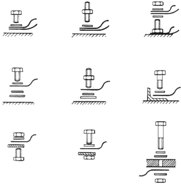
Figure description:
The image displays nine diagrams of typical earthing arrangements involving fasteners and electrical terminals. Key entities and features include:
- Fasteners: Hexagonal head bolts and studs with nuts.
- Washers: Flat circular components positioned between the fastener head/nut and the terminal.
- Terminals: Curved cable lugs or eyelet connectors representing electrical leads.
- Substrates: Horizontal mounting surfaces, including flat plates, angled brackets, and cross-sectioned panels with pre-drilled holes.
- Configurations:
- Top row: Surface mounting with bolts or studs.
- Middle row: Mounting with additional spacing washers or onto angled brackets.
- Bottom row: Through-hole mounting and double-sided connections through a central panel.
Figure 10-2 - Typical Earthing Arrangements
10.2.5 Handling Size
There are clear advantages in handling fasteners that have reasonable size. Very small fasteners are more easily dropped or damaged and assembly tends to be more time consuming when they are used. Additionally, very small fasteners cannot be reliably torque tightened. M4 is commonly held to be the smallest useful fastener size for general use, although other constraints can dictate the use of smaller fasteners. Thus, low duty joint often occur for ease of handling reasons, typical examples being are cable and pipe clamps, see Figure 10-3.
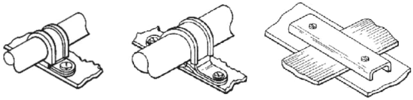
Figure description:
The image shows three technical line drawings of mechanical clamp connections:
- Left Image: A P-style clamp securing a single cylindrical pipe or cable to a flat surface with one screw fastener.
- Center Image: A saddle-style clamp securing a single cylindrical pipe or cable to a flat surface with two screw fasteners (one on each side.
- Right Image: A U-channel or bracket securing a flat rectangular component to a base surface using two screw fasteners.
Figure 10-3 - Typical Low Duty Clamp Connections
10.2.6 Stiffness
The fastener size or number of fasteners used has a significant effect on the joint stiffness, it can also affect the stiffness of the mounted assembly. For example, by increasing the number of mounting points for an equipment box, its stiffness when mounted can increase, eliminating the need for complex stiffening structure within the box (thus saving weight and reducing cost).
10.2.7 Tolerances
In order to reduce costs it is important to minimise the tolerances. The larger the fastener, the larger the acceptable hole clearance whilst maintaining sufficient under-head bearing area, and hence the greater the misalignment that can be accommodated. This is particularly important for large lightweight assemblies where the distance between the mounting hole centres can be large, hence requiring relatively large positional tolerance to avoid the need for excessive manufacturing precision.
10.2.8 Redundancy
For some structures it can be deemed prudent to add additional fasteners to maintain the structural integrity should a fastener fail. This is more important in joints with few fasteners and hence can lead to a substantial reduction in duty.