5.4.1 Fastener Geometry
For a fastener analysis several dimensions are important. These are depicted in Figure 5-5 and Figure 5-6.
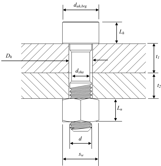
Figure description:
Key Entities:
- Fastener (bolt consisting of a head, shank, and threaded section.
- Nut threaded onto the bolt.
- Two joined plates represented with cross-hatching.
Labeled Dimensions:
- : Diameter of the bolt head.
- : Height of the bolt head.
- : Diameter of the hole through the plates.
- : Diameter of the bolt shank.
- : Thickness of the upper plate.
- : Thickness of the lower plate.
- : Height of the nut.
- : Diameter of the bolt threads.
- : Width across the nut.
Figure 5-5 – Fastener Dimensions
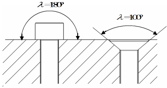
Figure description:
The image depicts two fastener head configurations with their respective under-head bearing angles :
- Left Configuration: A protruding cylindrical fastener head (e.g., a cap screw shown with an angle .
- Right Configuration: A countersunk fastener head shown with an angle .
- Entities:
- : Represents the under-head bearing angle.
- Fastener Heads: One flat-bottomed protruding head and one tapered countersunk head.
- Substrate: Indicated by diagonal hatching.
Figure 5-6 – Definition of the under-head bearing angle

Figure description:
Title: Table 5-2 - Physical Dimensions of Fasteners
Table Content:
- Variable:
- Description: Nominal diameter of the fastener.
- Variable:
- Description: Pitch diameter of the male thread.
- Variable:
- Description: Minor diameter of the male thread.
- Variable:
- Description: Diameter of the clearance hole in the clamped parts.
- Variable:
- Description: Outer diameter of the bearing surface of the fastener head or the nut.
- Variable:
- Description: Thread pitch.
- Variable:
- Description: Total length of the fastener.
- Variable:
- Description: Length of the unthreaded part of the fastener shank.
- Variable:
- Description: Length of the threaded part of the fastener shank.
- Variable:
- Description: Length of the thread engagement.
- Variable:
- Description: Width across flats (for hexagonal heads or nuts.
Entities Visible:
- Variable symbols (left column
- Descriptive definitions (right column
- Table identifier (Table 5-2
Table 5-2 shows the definitions of the physically measurable fastener variables used in this handbook. Some of these are omitted from Figure 5-5 for clarity.
| Variable | Definition | Notes | |
|---|---|---|---|
| p | Pitch of thread | ||
| h | Height of the basic thread | ||
| d | Nominal fastener diameter | Outside diameter of thread | |
| d0 | Diameter at smallest cross-section of fastener shank | ||
| d3 | Minor diameter of thread | For the true thread, not the basic profile | |
| dsha | Shank diameter | For necked-down fasteners | |
| duh,brg | Outer diameter of bearing area | Either under a head or under a nut | |
| Dh | Nominal diameter of hole in flange | ||
| A0 | Smallest cross-section of fastener shank | ||
| A3 | Cross-sectional area at minor diameter of fastener thread | ||
| λ | Under-head bearing angle | Always 100° for countersunk aerospace standard fasteners (right side of Figure 5-6) | |
| sw | Size of wrench | Across flats dimension of either a head or a nut | |
| Variable | Notation | Equation | |
| Pitch diameter | d2 | = d - 0,64952 p | [5.4.1] |
| Minor diameter | d3 | = d - 1,22687 p | [5.4.2] |
| Diameter used for stress calculation | dS | = 0,5 (d2 + d3) (for M type thread) | [5.4.3] |
| = see stress area below (for MJ type thread) | [5.4.4] | ||
| Diameter used for stiffness calculation | dsm | = d3 | [5.4.5] |
| Effective diameter of friction under head or nut | duh | = 0,5 (Dhead + Dh) | [5.4.6] |
| Stress area | AS | = 0,25 π dS2 (for standard fasteners, M type thread) | [5.4.7] |
| Variable | Notation | Equation | |
| 0,25π(d3)2 [2-(d3/d2)2] (for standard fasteners, MJ type thread) | |||
| = 0,25 π d02 (for reduced shank fasteners) | [5.4.8] | ||
| Stiffness area | Asm | = 0,25 π dsm2 | [5.4.9] |
| Smallest cross-section of fastener shank | A0 | = 0,25 π d02 | [5.4.10] |
| Minor diameter of the female thread | D1 | = d – 1,0285 p | [5.4.11] |
5.4.2 Thread Geometry
Figure 5-7 shows the geometric definition of the metric (M and MJ) threads. Both the male and female threads are based on the “Base Profile” shown in the left of the figure. The base profile defines the maximum spatial envelope of the male threaded part (normally the fastener itself), and the minimum spatial envelop of the female threaded part (normally the nut or threaded hole). The exact thread
profiles are defined in the relevant standards. The only difference between M and MJ type threads is the thread root radius, which is larger (to give improved fatigue performance) in the MJ type thread.
Table 5-3 shows the definitions of the derived fastener variables used in this handbook.
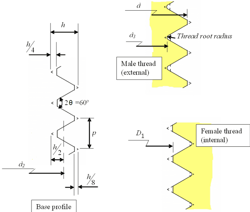
Figure description:
Key Entities and Dimensions:
-
Base profile:
- : Overall thread height.
- : Height from crest to truncation.
- : Height to pitch line.
- : Height from root to truncation.
- : Thread angle.
- : Thread pitch (distance between successive threads.
- : Pitch diameter dimension.
-
Male thread (external:
- : Major diameter dimension.
- : Minor diameter dimension.
- Thread root radius: Indicated at the base of the male thread profile.
-
Female thread (internal:
- : Minor diameter dimension.
Figure 5-7 – Thread Geometry
Table 5-3 - Derived Dimensions for Metric Fasteners
In general, it is important to find the correct equation in the relevant fastener technical specification, e.g. ISO 9152 for Titanium fasteners (Reference 5.1).
For unified threads (UNC, UNF, etc) the same equations apply except that the pitch, p, is not normally given in the fastener specification. In order to use the above equations provided in Table 5-3, it is necessary to calculate first the pitch by inverting the ‘threads per inch’ specification, which is given in the thread designation.
It is also important to take into account tolerance information in determining some or all of the dimensions used for stress calculations.
ISO 5855 (Reference 5.2) specifies the MJ-type thread, which is specially suited for aerospace applications and has a larger diameter at the thread root to improve the fastener’s fatigue life. The UNJ thread is the analogous modification for unified threads.