9.4.1 Overview
When the line of action of the applied shear load FQ does not pass through the centroid of a fastener group the joint is said to be eccentrically loaded. A typical eccentrically loaded shear joint is shown in Figure 9-23.
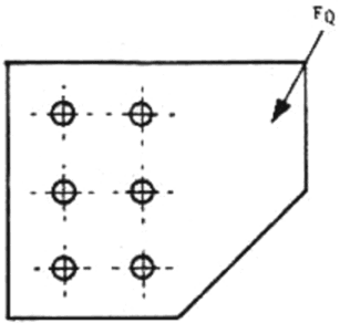
Figure description:
- Plate Structure: A five-sided polygonal plate or flange.
- Fastener Holes: Six circular holes arranged in a grid of three rows and two columns.
- Centerlines: Dashed vertical and horizontal lines intersecting at the center of each hole.
- Applied Load (: A force vector represented by an arrow pointing diagonally downward and to the left, applied at the upper-right corner of the plate.
Figure 9-23 - A Typical Eccentric Loaded Shear Joint
The type of load felt by individual fasteners depends whether the joint is operating as a friction grip or as a bearing type joint. The load-rotation curve for a typical joint loaded through friction grip and into bearing is shown in Figure 9-24.
Before the joint slips, the flanges are assumed deform together as a single elastic body. After the onset of slippage it is important to assume that all loads are transmitted via the bearing load paths.
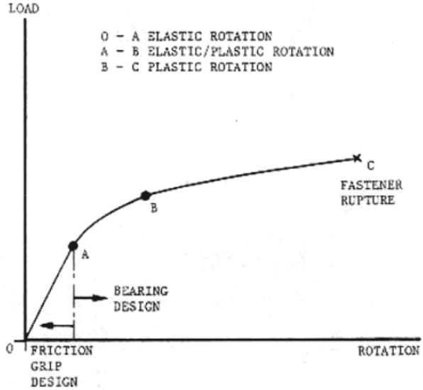
Figure description:
Load-Rotation Curve for Fasteners
LOAD vs ROTATION
Legend
- O - A ELASTIC ROTATION — color: black; symbol: text
- A - B ELASTIC/PLASTIC ROTATION — color: black; symbol: text
- B - C PLASTIC ROTATION — color: black; symbol: text
Annotations
- O - A ELASTIC ROTATION (text_label - position: top center)
- A - B ELASTIC/PLASTIC ROTATION (text_label - position: top center)
- B - C PLASTIC ROTATION (text_label - position: top center)
- FASTENER RUPTURE (text_label - position: Point C)
- FRICTION GRIP DESIGN (text_label - position: x < Rotation at A)
- BEARING DESIGN (text_label - position: x > Rotation at A)
- Vertical line from Point A to axis (vertical_line - position: Rotation at Point A)
| ROTATION (relative) | LOAD (relative) | Label | Description |
|---|---|---|---|
| 0.0 | 0.0 | O | Origin |
| 1.5 | 3.5 | A | End of elastic rotation |
| 3.5 | 5.5 | B | End of elastic/plastic rotation |
| 10.0 | 7.5 | C | Fastener rupture point |
Notes: The chart illustrates the behavior of a fastener under load, divided into elastic, elastic/plastic, and plastic rotation regions. It distinguishes between friction grip design and bearing design based on the elastic limit point A.
Figure 9-24 - Load v Rotation Curve for a Typical Eccentric Loaded Shear Joint
9.4.2 Fastener Group Centroid
The centroid of the fastener group can be determined by assuming any two axes X and Y and applying the equations,
where xi and yi are the coordinates of the i'th fastener, and Asha,i is its shank area.
In some cases symmetry can also be used to determine the fastener group centroid.
9.4.3 Bearing Design of Eccentric Shear Joints
In Figure 9-23 the eccentric load F, can be resolved to the centroid of the fastener group as a force FQ and a moment MQ = FQ e (where e is the eccentricity of loading). Each fastener experiences a load due to F (in a direction parallel to it) and a load due to M acting in a direction perpendicular to a line passing through that fastener’s centre and the centroid of the fastener group.
The externally applied shear force can then be distributed amongst the fasteners proportionally to their shear areas according to,
where Asha,i is the shank area of the i’th fastener, and m is the total number of fasteners.
Similarly, the applied moment MQ can be distributed amongst the fasteners proportionally to their bearing and shear areas and to their distance from the centroid according to,
is the distance of the i'th fastener from the centroid.
The force vectors resulting from Equation [9.4.3] act parallel to the externally applied shear load. The force vectors resulting from Equation [9.4.4] act perpendicularly to the moment arm from the fastener group centroid to the relevant fastener. The shear load acting on each fastener is determined by the vectorial addition of these two forces.
Equation [9.4.4] uses the fastener shank areas () as the weighting factor for the load division. However, in some cases the bearing area and fastener stiffness can also be significant (e.g. for groups of dissimilar fasteners or when the flange thickness is not constant). In such cases it is recommended to replace the area, , with the strength of the fastener-hole pair, which is given by,
where Fbr,i is the ultimate bearing strength of the i'th hole (calculated using Section 9.3.4) and Fb,i is the ultimate shear strength of the i'th fastener (calculated using Section 9.3.2).
Using the shear force resulting from equation [9.4.3], it is important to calculate the relevant margins of safety for each fastener according the complete set of bearing joint analysis methods in Section 9.3.
A worked example of eccentric bearing joints is given in Section 9.5.3.
9.4.4 Friction Grip Design of Eccentric Shear Joints
9.4.4.1 Overview
In a friction grip joint the load is transmitted between the flanges via frictional forces at the clamped interstice. Hence, the rotational slip resistance is needed to estimate the loading capacity of the joint. This is calculated in Reference 9.2 by assuming that the slipping movement is about an instantaneous centre of rotation. The location of the centre of rotation depends on the fastener pattern and the line of action of the applied load, as illustrated in Figure 9-25.
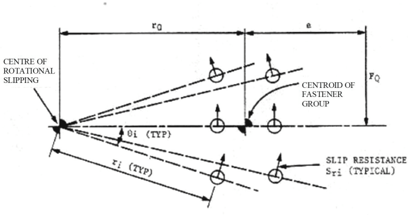
Figure description:
Key Entities:
- Centre of Rotational Slipping: The origin point on the far left from which radial lines originate.
- Centroid of Fastener Group: The geometric center of the fastener pattern.
- Fastener Group: Six circular fasteners arranged in two vertical columns.
Visible Parameters and Variables:
- : Horizontal distance between the centre of rotational slipping and the vertical axis of the fastener group centroid.
- : Horizontal distance (eccentricity from the fastener group centroid axis to the line of action of force .
- : Vertically applied external force.
- (TYP: Radial distance from the centre of rotation to an individual fastener.
- (TYP: Angular displacement of a fastener's radial line from the horizontal axis.
- Slip Resistance (TYPICAL: Force vectors acting on each fastener, shown perpendicular to their respective radial lines .
Figure 9-25 - Shear Resistance Relative to the Centre of Rotation
It is assumed that, at the onset of slipping, the magnitudes all fastener shear loads are equal. Thus, the slip resisting force transmitted by fastener i is given by;
S , i S r m [9.4.6]
where Sr is the overall slip resistance of the joint as calculated from Equations [9.2.1], [9.2.2] or [9.2.3], (see Section 9.2.).
It is also assumed that, at the onset of slipping, each fastener carries a reaction force in a direction perpendicular to the radial line emanating from the centre of rotation (see Figure 9-25). The angle of the radial line is given by;
where xi and yi are the coordinates of fastener i and x0 and y0 are the coordinates of the centre of rotation, which can be found by the iterative process described below in Section 9.4.4.2.
9.4.4.2 Determination of the Centre of Rotation
A trial centre of rotation is chosen and used as the origin for X and Y axes. Then the following three equilibrium equations are checked;
where i θ is a function of the assumed centre of rotation.
It is important to use then a suitable iterative algorithm to find a centre point that satisfies all three equations.
Due to symmetry, the centre of rotation for the fastener group shown in Figure 9-25 lies on a line, which is perpendicular to the externally applied load and passing through the centroid of the fastener group. Therefore, in that case, the search for the centre of rotation only needs variation of one parameter. If the fastener pattern is non-symmetric (with respect to the applied load), the location of the centre of rotation is unknown in both the X and Y directions.