9.2.1 Design Principles
Friction grip design relies on a sufficiently high clamping force maintained by the fasteners to prevent transverse slippage of the clamped plates due to transverse load. It has the principal advantage that, providing slip does not occur, the fastener feels only the tensile preload in the case of symmetric joints (double shear and two faying surfaces) shown in Figure 9-3. In the unsymmetrical case of a single faying surface (single shear) shown in Figure 9-5 and Figure 9-6 the joint’s deformation creates relatively small tension load in the fasteners, which is usually insignificant. This handbook addresses the load transfer by the friction between the clamped parts as a basic design principle. Note that this approach is not followed by other standards like, e.g., NASA-STD-5020 that, for human spaceflight missions, does not allow to use friction to react applied shear forces between the clamped parts for ultimate loads assessment.
There are also some other additional advantages provided by the friction grip design approach:
- • Large clearance holes can be used, which facilitates manufacture, assembly and interchangeability.
- • For stiffness and load transfer considerations the mating flanges in a friction grip joint can be treated as a single elastic body.
- • In the absence of slip, vibration loosening does not occur.
- • Friction grip design is simple to implement since the fastener preload, provided it is above the slip threshold, is not critical. Therefore, friction grip fasteners can be sized on tensile clamping strength alone.
- • Since there is generally additional strength in the bearing load (at least before its ultimate failure), friction grip design can be considered “fail-safe”.
It is important that for friction grip joints the clamped parts strength are calculated by the “net section tension” method (see Section 9.3.3).
If desired, a friction grip joint can also be analysed for slippage into bearing using the methods in Section 9.3.
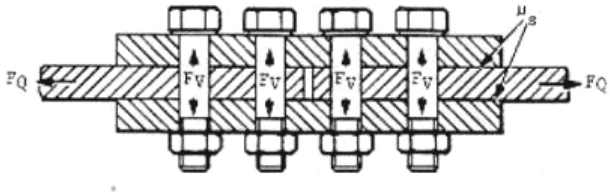
Figure description:
The image depicts a cross-sectional diagram of a symmetrical shear joint, identified as Figure 9-3. Key visible entities and details include:
- Fasteners: Four bolts with nuts clamping three plates together.
- Forces (: Internal tensile preload indicated by vertical arrows labeled "" within each bolt shank.
- Transverse Loads (: Horizontal shear forces applied to the central plates, labeled as "" at both ends of the joint.
- Faying Surfaces (: The contact interfaces between the central plate and the outer plates, labeled with the coefficient of friction symbol "".
- Joint Configuration: A double-shear arrangement where a central plate is sandwiched between two outer plates, secured by multiple fasteners.
Figure 9-3 - A Symmetrical Shear Joint
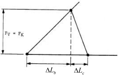
Figure description:
Mechanical Force-Deformation Schematic
Force-Deformation Diagram
Annotations
- F_V = F_K (vertical_line - position: Vertical distance from the base line to the peak dot)
- ΔL_b (horizontal_line - position: Horizontal distance from the left vertex to the vertical dashed altitude line)
- ΔL_c (horizontal_line - position: Horizontal distance from the vertical dashed altitude line to the right vertex)
- Dashed Vertical Line (vertical_line - position: From the peak vertex to the base line at x = ΔL_b)
- Peak Extension Line (line - position: A line segment extending from the peak vertex upwards and to the right)
| Point | X-Coordinate | Y-Coordinate |
|---|---|---|
| Left Vertex (Origin) | 0 | 0 |
| Peak Vertex | ΔL_b | F_V = F_K |
| Right Vertex | ΔL_b + ΔL_c | 0 |
| Foot of Altitude (on Base) | ΔL_b | 0 |
Notes: The diagram is a standard joint clamping schematic (Rötscher diagram representing the relationship between preload force (F_V, clamping force (F_K, bolt elongation (ΔL_b, and compression of the clamped parts (ΔL_c.)))))
Figure 9-4 - The Joint Diagram for Each Fastener in Figure 9-3
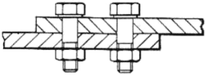
Figure description:
- Schematic diagram of a lap joint.
- Two overlapping plates secured together.
- Two hexagonal head bolts passed through both plates.
- Each bolt is secured with a hexagonal nut at the bottom.
- Cross-hatching (diagonal lines indicates the section of the two joined plates.
Figure 9-5 - Typical Unsymmetrical Friction Grip Shear Joint
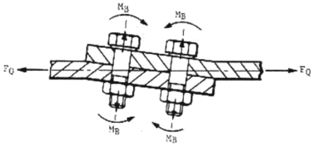
Figure description:
Entities:
- Two bolt and nut assemblies
- Two overlapping plates
Labeled Features:
- : Horizontal forces applied in opposite directions to the plates.
- : Bending moments shown as curved arrows at the bolt heads and nuts.
- Straight arrows pointing outward along the longitudinal axis of each bolt, indicating axial tension.
- The plates and fasteners are shown in a tilted orientation, depicting deformation under load.
Figure 9-6 - Fastener Bending and Tension in an Unsymmetrical Shear Joint
9.2.2 Slip Resistance
9.2.2.1 Overview
Slip resistance depends on the friction force at the interface’s faying surfaces. This force is in turn dependent on the fastener clamping load and the friction coefficient at those faying surfaces.
9.2.2.2 Pure Shear Loading
When no external axial load is applied to the joint, the clamping load is equal to the sum of the preloads and the slip resistance is given conservatively by,
where; µ is the minimum slip coefficient of the flange interface, x is the number of faying surfaces, s and FV,min,i is the minimum preload in the ith fastener taking into account variations in preload and thermal effects (see Section 6.3.5 and 6.4).
If all of the fasteners in the joint have the same minimum preload, FV,min , Equation [9.2.1] is simplified to,
where m is the number of fasteners in the joint.
In multi-fastener joints Equation [9.2.2] can be overly conservative since it assumes that all fasteners are tightened to the lower bound of their preload range. Therefore, if the joint has enough fasteners (typically 5 or more), the slip resistance of the joint can be calculated with,
where is the nominal preload
In case of local bending moment, the impact can be a variation of the spread of the local pressures, without influence on the sum of the compression pressures (due to fasteners preload), and with an increase of the maximum local pressure, which can only have a positive impact on the friction coefficient. So the local bending moment can be neglected.
9.2.2.3 Slip Resistance For Axial Loaded Joints
Provided the joint does not slip, the fastener can experience only tensile load. For the simple joints shown in Figure 9-7 the external axial load FA is partly absorbed in stretching the bolt but is mainly absorbed in releasing the clamped parts. The axial load reduces the interface clamping, FK , and thereby reduces the shear load capacity of the joint.
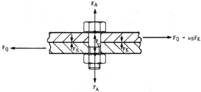
Figure description:
Entities:
- Bolt and nut assembly
- Two overlapping plates (flanges
- Force vectors
Labels and Formulas:
- : Upward and downward axial tension forces applied to the bolt head and nut.
- : Lateral shear forces applied in opposite directions to the plates.
- : Formula for lateral force on the right plate.
- : Compression forces acting between the plate surfaces.
- : Internal bolt force between the plates.
Figure 9-7 - Simple Friction Grip Joint with Added Tension Loading
A friction grip joint is considered to have failed when the joint has slipped. It is therefore necessary to ensure that,
where is the flange compression force.
The flange compression is relieved according to,
where the force ratio term Φ e, n takes into account any adjustments for the loading plane factor (see Section 7.5) or eccentricity (see Section 8.2.3).
The relationship between the axial load and slip resistance is linear (see Figure 9-8).
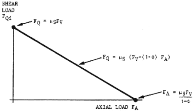
Figure description:
Shear Load vs Axial Load
Relationship Between Shear Load and Axial Load
Annotations
- FQ = mu_S * FV (text_label - position: y-intercept (FA = 0))
- FQ = mu_S * (FV - (1 - phi * FA (text_label - position: on the line)))
- FA = (mu_S * FV / (1 - phi (text_label - position: x-intercept (FQi = 0))))
| AXIAL LOAD (FA) | SHEAR LOAD (FQi) |
|---|---|
| 0 | mu_S * FV |
| (mu_S * FV / (1 - phi)) | 0 |
Notes: The chart illustrates a linear relationship between Shear Load (FQi and Axial Load (FA based on the equation provided. mu_S, FV, and phi are constants in the model.))
Figure 9-8 - Reduction of Shear Capacity with Increasing External Axial Load
9.2.2.4 Friction Coefficients at the Interface
Friction is subject to high variability. Therefore, to ensure safety in the design calculations, it is assumed that µ is at the minimum of its range, and it is important that the surface roughness of interfaces is s taken into account. It is important to remember that although an increase in surface roughness increases the slip coefficient, it also increases the preload loss due to embedding which can be the more important effect (see Section 6.4.2).
Annex C lists typical friction coefficients for commonly used joint materials.
9.2.2.5 Design Features that Increase Slip Resistance
The joint can be designed with specific features that increase its slip resistance such as those shown in Figure 9-9. However, the calculation of the shear capacity of such joints is beyond the scope of this document.
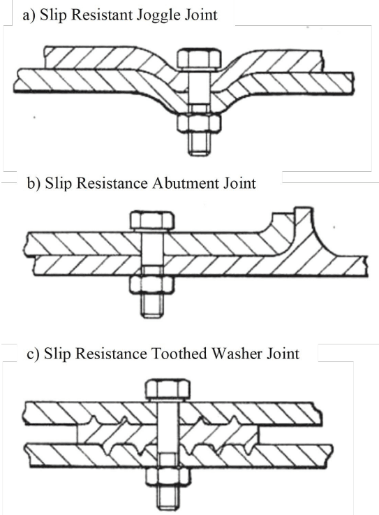
Figure description:
- a Slip Resistant Joggle Joint: Cross-section diagram showing two plates with a curved offset (joggle secured by a central bolt and nut.
- b Slip Resistance Abutment Joint: Cross-section diagram showing two flat plates where the top plate terminates at a vertical raised edge (abutment of the bottom plate, secured by a bolt and nut.
- c Slip Resistance Toothed Washer Joint: Cross-section diagram showing two flat plates with a double-sided toothed washer clamped between them, secured by a central bolt and nut.
Figure 9-9 - Joint Design Features that Increase Slip Resistance

Figure description:
Figure 9-10 - Shear Joint in Bearing
Key Entities:
- Upper flange
- Lower flange
- Fastener (bolt and nut
- Shear load arrows
Visible Details:
- A cross-section diagram of two overlapping flanges joined by a central fastener.
- Two horizontal arrows point in opposite directions, representing shear loads.
- The fastener shank is shown in physical contact with the edges of the holes in the flanges.
- The fastener assembly includes a bolt head, shank, and nut.
9.2.3 Friction Grip Strength Analysis
It is important that the strength analysis documentation for such a joint clearly identify it as a “friction grip joint“ and the margin of safety for slipping is stated.
The margin of safety for slipping is calculated taking into account the lowest possible preload, , and the safety factor for ultimate loads (see Table 5-4). It is defined as;
If the MoS for slipping is positive, the margin of safety on separation defined in Section 7.8 is also positive. If used, it is important to clearly state this fact in the strength analysis documentation.
It is important that the net tension section of each flange also have sufficient strength to carry the shear load. See Section 9.3.3 for the net section evaluation method.
It can also exist a design requirement that, if the friction grip joint slip into bearing, the joint does not fail in any of the other modes described in the next section for bearing joints.