7.8.1 Introduction
Under an externally applied tensile load it is generally required that no gapping occurs at any interstice between clamped parts in a joint (i.e. the clamping force does not reach zero). Many joints have additional requirements for a positive clamping force for sealing and other operational functions. Thus, the failure mode of joint separation is defined to occur when the clamping force is reduced to its critical level, FK,req (which is greater than or equal to zero).
The joint diagram at the critical condition for separation failure is depicted in Figure 7-25. It can be seen that, under the action of FA , the compression in the clamped parts is reduced from the initial preload of FV,min to the minimum specified level of FK,req . Any increase in FA results in insufficient compression in the clamped parts, thereby constituting failure by separation.
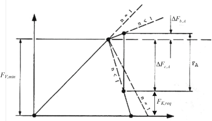
Figure description:
Influence of the load introduction factor n on bolt and clamping force components
Force-Deformation Diagram of a Bolted Joint
Legend
- n = 1 — color: black; symbol: Dashed line
- n < 1 — color: black; symbol: Dashed line
- Stiffness lines — color: black; symbol: Solid line
Annotations
- (vertical_line - position: Vertical span on the left axis representing initial preload)
- (vertical_line - position: Vertical span representing total external axial force)
- (vertical_line - position: Top segment of corresponding to bolt force increase)
- (vertical_line - position: Bottom segment of corresponding to reduction in compression)
- (vertical_line - position: Remaining force at the lower clamping limit)
| Variable | Description |
|---|---|
| Minimum preload force | |
| External axial force applied to the joint | |
| Increase in bolt force due to the external load | |
| Decrease in clamping (compression force due to the external load ) | |
| Required clamping force remaining in the joint | |
| Load introduction factor, where is application at the ends and is application inside the parts |
Notes: The diagram illustrates the mechanical relationship between preload, external loading, and the resulting forces in the bolt and clamped parts. It specifically highlights how the load introduction factor 'n' modifies the slope of the force distribution lines.
Figure 7-25 - Joint Diagram at Onset of Separation Failure
7.8.2 The Margin of Safety for Joint Separation
The MoS for joint separation is not intended to cover the case of slipping of a friction grip joint. The appropriate MoS for slipping is defined in Section 9.2.1.
The Margin of Safety for joint separation is given by,
where sfsep is the safety factor defined for separation as defined in Table 5-4,
and Φn is the force ratio defined in equation [7.4.6].