9.1.1 Overview
Shear loaded joints are often used to connect sheet or plate material and usually have multiple fasteners. These types of joints transmit loads transverse to the longitudinal of the fastener. A typical shear joint is illustrated in Figure 9-1.
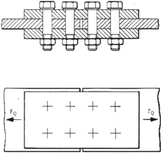
Figure description:
- Top Diagram (Cross-Section: Shows four vertical bolts with nuts securing three layers of material.
- Bottom Diagram (Top View: Displays a rectangular plate with eight fastener locations marked by "+" symbols, arranged in a 2x4 grid.
- Force Indicators: Opposing horizontal arrows labeled show shear force applied to the central and outer plates.
- Entities: Bolts, nuts, material plates, and force vectors (.
Figure 9-1 - Typical Double Lap Shear Joint
Shear loaded joints can be designed according to two fundamentally different philosophies.
- a. Friction grip (or slip resistant) design
- b. Bearing type (or slipped joint) design
As the name suggests, friction grip joints rely on friction between the flanges to transmit the shear loads. Bearing joints rely on the fasteners to transmit the shear loads, which are generated at the interface between the fastener shank and the flange hole.
In practice joints can generally behave as friction grip joints until the load is sufficiently high to slip the flanges. Figure 9-2 shows a typical force vs. extension curve for a shear joint showing how a friction grip joint can “slip” into a bearing joint configuration as the transverse force FQ increases. The extent of the deformation occurring during the slip depends on the fastener pattern, the hole clearance and the alignment of the holes.
For the reasons explained below in Section 9.2.1, when feasible, friction grip design is the preferred option for joints in spacecraft structures.
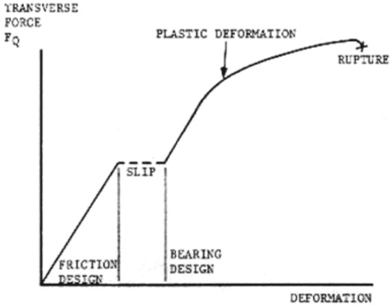
Figure description:
Structural Load-Deformation Characteristic Curve
TRANSVERSE FORCE FQ vs. DEFORMATION
Annotations
- FRICTION DESIGN (text_label - position: Label under the first linear segment of the curve)
- SLIP (text_label - position: Label within the horizontal plateau region)
- BEARING DESIGN (text_label - position: Label at the start of the second rising segment)
- PLASTIC DEFORMATION (text_label - position: Indicated with an arrow pointing to the upper curved portion of the plot)
- RUPTURE (text_label - position: Marked with an 'X' at the terminal point of the curve)
- First Phase Boundary (vertical_line - position: Vertical line separating Friction Design and Slip regions)
- Second Phase Boundary (vertical_line - position: Vertical line separating Slip and Bearing Design regions)
| Deformation (Relative Units) | Transverse Force FQ (Relative Units) | Notes |
|---|---|---|
| 0 | 0 | Origin |
| 2.5 | 4 | End of Friction Design / Start of Slip |
| 3.5 | 4 | End of Slip / Start of Bearing Design phase |
| 5 | 7 | Transition to Plastic Deformation |
| 6.5 | 8.5 | Plastic Deformation region |
| 8.5 | 9.3 | Near peak load |
| 9.5 | 9.4 | Rupture (marked with X) |
Notes: The chart illustrates the typical load-deformation behavior of a connection, transitioning from friction-controlled resistance to a slip phase, followed by bearing resistance, plastic deformation, and eventual rupture.
Figure 9-2 - Load Deformation Curve for a Fastener in Direct Shear
9.1.2 Analysis Approach
Friction grip joints and bearing joints need analysis of different failure cases. The margins of safety related for shear loads that need to be calculated for each type of joint are summarised in Table 9-1.
| Margin of safety | Friction grip joint | Bearing joint | Refer to section |
|---|---|---|---|
| Slipping | Yes | No | 9.2.2 |
| Fastener shear | No | Yes | 9.3.2 |
| Hole bearing | No | Yes | 9.3.4 |
| Flange net tension section | Yes | Yes | 9.3.3 |
| Flange crushing | Yes | No | 7.11 |
| Fastener combined bending and shear | No | Yes | [1] |
[1] This failure mode is not covered in this version of the handbook.
Figure description:
- Text: ECSS
- Key Entities:
- Letter "E" in italicized serif font.
- Letters "CSS" in italicized serif font.
- Visual Elements:
- The "E" is white and positioned within a white parallelogram with a blue border.
- The "CSS" is white and positioned within a blue parallelogram.
- The overall shape is a slanted rectangle divided into two sections.
- Colors: Blue and white.