7.14.1 Preload in a Concentric Axially Loaded Joint
7.14.1.1 Overview
The geometry of this example problem is shown in Figure 7-30.
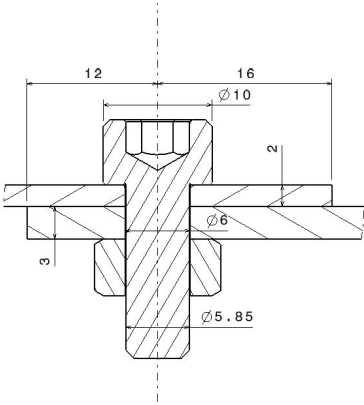
Figure description:
- Entities: Bolt, nut, two clamped plates, vertical axis of symmetry.
- Radial Dimensions:
- Inner plate edge to centerline: 12
- Outer plate edge to centerline: 16
- Vertical Dimensions:
- Top plate thickness: 2
- Bottom plate thickness: 3
- Diameters:
- Bolt head diameter: 10
- Shank diameter through plates: 6
- Lower shank diameter: 5.85
Figure 7-30 - Example problem of concentric axially loaded joint
7.14.1.2 Initial Data
The fastener to be used for this joint is a LN 29949 M6 x 14 with an anchor nut LN 29693. This fastener has the following material properties:
Table 7-5: Preload in a Concentric Axially Loaded Joint, fastener material properties
Material: A-286 steel Yield allowable: 950 MPa Ultimate allowable: 1100 MPa Shear yield allowable: 548 MPa Shear ultimate allowable: 655 MPa Young's modulus (): 201 GPa Thermal expansion coefficient (): 1,68e-5 K-1
The following thread parameters can be calculated using the standard relations for metric threads:
Table 7-6: Preload in a Concentric Axially Loaded Joint, Thread parameters
Thread pitch (): 1 mm (standard) Fastener nominal diameter (): 6 mm (M6 fastener) Pitch diameter (): 5,35048 mm Minor diameter (): 4,77313 mm Stress diameter (): 5,062 mm Cross-section area at minor diameter (): 17,894 mm² Stress area (): 20,123 mm²
The upper flange is 2 mm thick with an edge distance of 16mm. The lower flange is 3 mm thick with an edge distance of 12 mm. The diameter of the holes through the flanges is 6,5 mm.
The flanges have the following material properties:
Table 7-7: Preload in a Concentric Axially Loaded Joint, flange material properties
Material: Al 7075 T 7351 Young's modulus (): 71 GPa Thermal expansion coefficient (): 2,2e-5 K-1 Shear ultimate allowable: 262 MPa
| Symbol | Definition | Section |
|---|---|---|
| 613 MPa | ||
| 882 MPa | ||
| 524 MPa | ||
| 689 MPa |
The joint is assembled at a reference temperature of 21°C. The maximum operating temperature is 50° C and the minimum operating temperature is 4° C.
The joint is subjected to an external axial load of 1000N.
The strength of this structure is only verified by analysis. Thus, it is important that the safety factors for yield and ultimate loads are taken from Table 5-4. These values are then multiplied by the joint fitting factor of 1,15. Thus, the safety factors to be applied to the design justification are:
sfy = 1,25 x 1,15 = 1,4375 sfult = 2 x 1,15 = 2,3
7.14.1.3 Calculation of the Nominal Preload
For the preload ratio, the default value of 0,8 is chosen. With this starting point the preload stress is calculated,
With this, the nominal preload can be calculated,
7.14.1.4 Calculation of the Force Ratio
First the compliance of the fastener has to be determined (see Section 7.5). The joint is nut-tightened and has a cylindrical fastener head. Therefore the appropriate substitution lengths from Table 7-1 are as follows:
Lh,sub = 0,4 d
Leng,sub = 0,5 d
Ln,sub = 0,4 d
Using these substitution lengths the fastener’s compliance can be calculated using equation [7.5.5],
where the modulus of elasticity of the nut is equal to that of the fastener.
It is assumed that the entire shank length is threaded, which leads to,
Therefore, the fastener compliance is evaluated as,
Now, the compliance of the clamped parts is calculated. The available diameter for compression cone is determined from the minimum edge distance,
Davail = 24 mm (minimal edge distance of 12mm occurs in upper flange)
The length of the compression zone is the full length through the clamped parts,
= 5 mm
The underhead bearing diameter is equal the diameter of the fastener head
Duh,brg = 10mm
The non-dimensional compression cone parameters x and y are evaluated as,
Thus, tan of the compression cone half angle is calculated from Equation [7.6.6],
The limit diameter of the compression cone is calculated with Equation [7.6.5], with w=1 for a nut- tightened joint:
The criteria in Section 7.6.3.4 are used to determine that the compression cone is fully developed since . Therefore, Equation [7.6.10] is used to calculate the compliance of the clamped parts,
The (basic) force ratio is now calculated using Equation [7.4.2],
The geometry of the joint is simple, so the loading plane factor, n, can be assumed 0.5 with adequate accuracy. Thus, the force ratio of the joint with loading plane adjustment is given by,
7.14.1.5 Calculation of the preload loss due to embedding
The preload loss due to embedding is assumed to be 5% of the nominal preload. Therefore,
7.14.1.6 Calculation of the thermal induced loads
This calculation is performed with Equations [6.3.23] and [6.3.24],
7.14.1.7 Calculation of the maximum and minimum preload
The following values of the underhead and thread friction coefficients are read from Annex B for the specific fastener and nut combination:
The following maximum and minimum prevailing torques are read from Table 6-2:
The effective diameter of the application of the underhead torque is determined using Equation [5.4.6],
The tan of the thread helix angle is determined using the relation in Equation [6.3.9],
The thread tooth angle is therefore,
Now a trial value of the maximum applied torque is set to 13,65Nm. Assuming a torque wrench scatter of 5%, this leads to a maximum applied torque of 14,3Nm and a minimum applied torque of 13,0Nm. The applied torque is specified as part of the manufacturing process so it is important that it is rounded to an accuracy of 0,1 Nm. The bolt utilization, torque and preload are directly linked with each other. Any of these parameters can be chosen as baseline for the bolt evaluation process and the other than calculated out of the selected one.
Now the maximum and minimum in-service preloads are calculated using Equations [6.3.14] and [6.3.15],
Finally, it is important to determine the margin of safety on the tightening process. The load in the fastener is composed of a tensile stress due to the preload and a torsional stress due to the applied torque. First the torsional stress is calculated.
The polar section modulus is calculated with equation [6.5.5], which considers the case of total plastic deformation (ultimate),
The minimum moment absorbed by friction under the fastener head is determined with Equation [6.5.3], with λ=180 degrees for a flat screw head
The maximum shear stress due to torsion is then calculated with Equation [6.5.2],
The maximum tensile stress is calculated with Equation [6.5.6],
Now the von Mises equivalent stress can be calculated using Equation [6.5.1],
The ultimate margin of safety on tightening is then calculated with Equation [6.5.8],
The next step in the analysis process is to check the shear pull-out of thread. Because the nut is made of the same material than the fastener (the nut is like the fastener made of A-286 steel.), the shear pull out of thread is not critical. Nevertheless, the following example shows a calculation of the nut’s pull-out strength.
7.14.2 Thread Shear Pull-Out Example
The thread of joints that use normed nuts of the same material grade as the fastener (or higher) can always be at least as strong as the fastener itself. However, an example of thread pull-out for such a joint is documented here to show the analysis process.
First, the effective length of the engaged thread is calculated with Equation [7.10.3]. The effective engaged thread length leff of the LN 29693 anchor nut is 5 mm (although the fastener protrudes beyond the length of the nut).
Now, the failure surface areas of the threads are calculated with Equations [7.10.2] and [7.10.8]. The pitch diameter of the female thread, , is equal to that of the fastener, .
The female-to-male thread strength ratio is calculated with Equation [7.10.7],
Now, the empirical coefficients and are calculated using Equations [7.10.4] to [7.10.6]. The joint uses an anchor nut, and therefore the wrench size, , is not defined. Therefore, in order to evaluate the constant , it is important to use the outer diameter of the anchor nut, which is 7,5 mm.
:
Now the critical axial forces for shear pull-out of the female (nut) thread is determined with Equation [7.10.1],
The empirical coefficient is calculated using Equation [7.10.14],
Now the critical axial forces for shear pull-out of the male (bolt) thread is determined with Equation [7.10.12],
That gives all necessary input for the calculation of the margins of safety for thread failure under external and overall axial loads with Equations [7.10.16] and [7.10.17], with
With equivalent material class, the nut thread pull-out is not verified because covered by the screw strength.