13.3.1 Introduction
Stress Corrosion Cracking (SCC) occurs where certain alloys are subjected to a continuous tensile stress in the presence of a specific corrosive environment. The failures appear to be of a brittle type even where the material is recognised to be ductile. Surfaces in the region of the crack do probably not appear
affected by general corrosion that often makes SCC more difficult to diagnose. Time to failure is a matter of minutes under severe conditions, or years when conditions are less severe.
SCC is often associated with aerospace structures constructed from high strength materials and operating at high stresses. The Apollo Program suffered many SCC failures and much was learned about the design of space structures as a result (see Reference 13.2). Subsequently NASA issued design criteria for controlling SCC (Reference 13.3), to be met by all contractors for NASA flight hardware. It contains a list of materials that are resistant to SCC and also those which are most susceptible. A similar document called ECSS-Q-ST-70-36 “Material Selector for Controlling Stress Corrosion Cracking” exists within ECSS. (Reference 13.4).
The following Sections aim to highlight the aspects of SCC relevant to threaded fastener joints and to make designers aware of the methods available to avoid or reduce the occurrence of SCC.
13.3.2 Factors Affecting Stress Corrosion Cracking
13.3.2.1 Overview
The prerequisites for SCC are as follows:
- a. a susceptible material
- b. a specific corrosive environment
- c. a tensile stress
Each of these is discussed in Sections 13.3.2.2 to 13.3.2.4 below.
13.3.2.2 The Susceptibility of Materials to SCC
It is worth mentioning that SCC is sometimes more generally named environmentally assisted cracking (EAC). The effect of alloy composition and metallurgical condition (grain size and orientation, distribution of precipitates, etc.) on SCC is sufficiently understood to specify certain preferred alloys and treatments to minimise the effect of SCC (see Reference 13.3).
In high strength aluminium alloys the effects of heat treatment and cold work are significant in determining resistance to SCC. For example when wrought aluminium products are manufactured by rolling, extrusion or drawing the alloy microstructure becomes distorted into elongated grains in the direction of working. This is designated the longitudinal direction, the width of the sheet is the transverse direction, and the thickness is designated the short transverse direction (as shown in Figure 13-2 for a number of section shapes).
Figure description:
The provided image contains the following text:
- ECSS (in white letters on a purple parallelogram background)
- E (in purple italicized letter on a white background)

Figure description:
The provided image illustrates grain orientations in standard wrought forms through three main categories:
1. Sheet and Plate
- Direction of Rolling: Aligned with the Longitudinal axis.
- Long Transverse: Across the width of the plate.
- Short Transverse: Across the thickness of the plate.
2. Extruded and Drawn Tube
- Direction of Extruding or Drawing: Aligned with the Longitudinal axis.
- Long Transverse: Circumferential/tangential direction.
- Short Transverse: Radial direction through the wall thickness.
3. Rolled and Extruded Rod Bar and Thin Shapes
- Direction of Rolling or Extruding: Aligned with the Longitudinal axis.
- Transverse/Long Transverse/Short Transverse: Identified for various geometries including cylindrical rods, square bars, rectangular bars, and L-shaped angles.
4. Extruded Thick and Complex Shapes
- Direction of Extruding: Indicated by a diagonal arrow.
- Note: Shaded areas represent transverse orientations; other areas follow the conventions established in the previous sections.
Figure 13-2 - Grain Orientations in Standard Wrought Forms
Material properties vary depending on the direction of testing with the longitudinal direction being strongest. The short transverse direction is usually the weakest and as a result is most prone to the effects of SCC. It is therefore desirable to design components that are not heavily stressed in the short transverse direction. Figure 13-3 and Figure 13-4 illustrate examples of poor joint design that can lead to high stresses in the short transverse direction.

Figure description:
-
Entities Visible:
- T-shaped cross-section profile.
- Internal concentric contour lines representing grain flow.
- Arrows pointing to specific grain flow orientations.
- Dashed line indicating the machined angle location.
-
Text Details:
- TRANSVERSE DIRECTION: Indicated by an arrow pointing to the central vertical section.
- SHORT TRANSVERSE DIRECTION - VERTICAL: Indicated by an arrow pointing to the vertical grain orientation in the center.
- LONG TRANSVERSE DIRECTION - HORIZONTAL: Indicated by an arrow pointing to the horizontal grain orientation in the base.
- SCHEMATIC OF GRAIN ORIENTATION: Label for the contour lines within the T-shape.
- LOCATION OF MACHINED ANGLE WITH RESPECT TO TRANSVERSE GRAIN FLOW IN THICK TEE: Caption describing the overall illustration.

Figure description:
Key Information:
- Entities:
- Rigid Member: Two components labeled as such, one vertical and one horizontal.
- Fasteners: Bolts and nuts shown securing a bracket to the rigid members.
- Bracket: An L-shaped component connecting the two rigid members.
- Labels and Annotations:
- Rigid Member: Points to the main structural components.
- Angular Mismatch (Can also happen with parallel gap: Points to the gap between the vertical rigid member and the bracket.
- High Assembly Stress in Short Transverse Direction: Points to the bend/corner of the bracket where it is fastened to the horizontal member.
Figure 13-3 - Assembly Stress Resulting from Mismatch
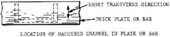
Figure description:
Entities and Labels:
- Thick plate or bar: Represented by the overall rectangular cross-section.
- Short transverse direction: Indicated by a vertical double-headed arrow within the plate.
- Location of machined channel in plate or bar: Indicated by dashed outlines within the larger rectangular body.
Key Information:
- The diagram illustrates the cross-section of a thick plate or bar showing the placement of a machined channel.
- The "short transverse direction" is identified as the vertical orientation relative to the plate's thickness.
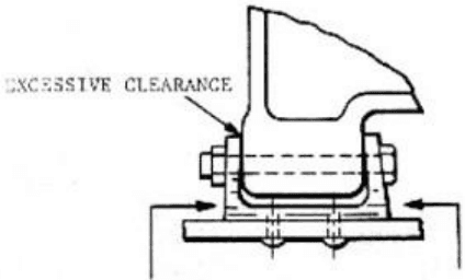
Figure description:
- Text: "EXCESSIVE CLEARANCE" with an arrow pointing to the gap between a vertical lug and the inner component.
- Entities:
- Inner component nested within a U-shaped outer lug.
- Fastener (bolt and nut passing through both components.
- Two horizontal arrows pointing inward toward the base of the outer lug walls.
- Fasteners (rivets or bolts at the bottom horizontal base.
Figure 13-4 - High Assembly Stresses in Short Transverse Direction
The short transverse direction of a forged component is perpendicular to its parting plane as shown in Figure 13-5. In this case any bush or fastener with an interference fit in the bore indicated is likely to accelerate failure by SCC.
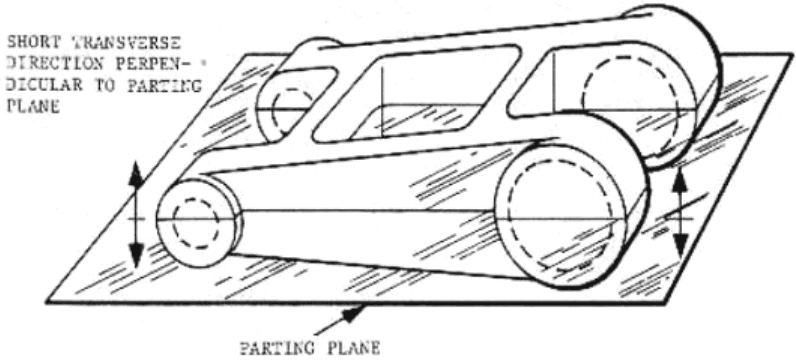
Figure description:
- Text: "SHORT TRANSVERSE DIRECTION PERPENDICULAR TO PARTING PLANE"
- Text: "PARTING PLANE"
- Key entities:
- Forged component with multiple cylindrical bores.
- A flat shaded surface labeled "PARTING PLANE" passing horizontally through the component.
- Vertical double-headed arrows indicating the short transverse direction.
- Dashed lines showing the internal circumference of the bores.
Figure 13-5 - Examples of Tensile Stresses in Short Transverse Direction Resulting from Assembly
Heat treatments have been developed to reduce the susceptibility of high strength aluminium alloys to SCC and it is important to specify these where possible.
When specifying alloys for use on space systems ECSS-Q-ST-70-36 on prevention of SCC is applicable (Reference 13.4). This document collects in a table the alloys with high resistance to SCC that can be used, and prescribes their conditions of use. Where an alloy is not listed and SCC data is not available, it is necessary to conduct suitable tests for SCC resistance, such as those given by ECSS-Q-ST-70-37 (see Reference 13.6). The results are submitted for approval on a Stress Corrosion Evaluation Form. A similar situation exists for material approval to NASA standards.
13.3.2.3 The Role of the Environment in Stress Corrosion Cracking
Environments that give rise to SCC are often specific to particular alloys, thus making SCC very difficult to predict unless tests have been conducted simulating the operating conditions or failures have been noted previously under similar conditions.
As the corrosive environment is essential for SCC to occur, it is important that the designer ensures that approved protective anti-corrosion coatings are specified.
13.3.2.4 The Influence of Stress on Stress Corrosion Cracking
The effect of applied tensile stress on SCC varies with materials. In some cases a threshold stress concentration factor Kiscc can be specified, below which failure by SCC cannot occur (see Section 11.3.5). In other cases, SCC occurs at all values of applied tensile stress, the time to failure being dependent on the stress level.
Tensile stresses in joint assemblies that can give rise to SCC can be imposed by several sources, in addition to the normal working stresses in the system. Misalignment or gaps between joint faces can cause high surface tensile stresses which when combined with an unfavourable grain orientation can result in rapid SCC failures. Such failures can be avoided by ensuring that gaps are properly shimmed, and the alignment of assemblies is checked.

Fasteners with substantial interference fits can impose high tensile stresses in the flange’s transverse grain direction, leading to longitudinal cracks. It is important to take care to specify alloys that are highly resistant to SCC in these regions.
In some cases, manufacturing processes can leave components with residual surface tensile stresses. Examples of such processes are bending, tube drawing, stretch forming, electro discharge machining (EDM) and some cutting operations. An indication of what level of residual stresses can be imparted by these operations is given in Reference 13.5. Heat treatment processes can also leave residual stresses, especially for components with complex shapes. It is important that all residual tensile stresses are reduced or eliminated by thermal treatments or by mechanical means.
Compressive surface stresses can be introduced in many components by shot peening. This process is very useful for controlling SCC in critical parts.