8.3.1 Overview
These joints have small contact areas at the interstice, leading to bending moments being transmitted through the flange. This results in the axis of the clamped parts being fixed rather than moving with change in external load FA (the case for joints with large areas of contact).
For this class of joints, the procedure for determining the flange compliance can be complex and time consuming. The theory presented in the following Sections applies to the special case of circular joints with cantilevered flanges. For more general cases with non-circular flanges it is recommended to use testing or FEM.
8.3.2 Compliance of Circular Flanges
8.3.2.1 Overview
References 8.3 and 8.5 give empirical relationships for joints with cantilevered circular flanges. This category of joints often occurs when gaskets or sealing rings are used.
8.3.2.2 Linear Superposition of Deformations
For cantilevered flange joints, three compliances are used in combination to describe the flanges’ bending displacements. Figure 8-14 indicates three modes of deformation that determine the deflections of the flange between the axis of the fastener and the axis of the clamped parts. These compliances are calculated as follows:
This is the compliance of the flanges under the preload taking into account the bending effects due to the eccentric clamping load. [8.3.1]
- This is the bending compliance of the flanges due to the corresponding portion of the applied load seen by the fastener. In other words it is the flange bending due to the couple with forces acting at the axes of the fastener axis and externally applied load. [8.3.2]
- This is the bending compliance of the flanges due to the load seen by the clamped parts and the corresponding portion of the applied load. In particular, it is the flange bending due to the couple with forces acting at the axes of the clamped parts and the externally applied load. [8.3.3]
Assuming no gapping occurs, the elongation of the flange due to the external load is the linear sum of the three extension modes of Figure 8-14, i.e.,
Thus the compliance of the flange is,
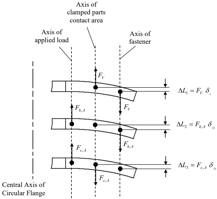
Figure description:
Key Entities and Axes:
- Central Axis of Circular Flange: Vertical dash-dot line on the far left.
- Axis of applied load: Leftmost dashed vertical line passing through force vectors.
- Axis of clamped parts contact area: Center dashed vertical line passing through force vectors.
- Axis of fastener: Rightmost dashed vertical line passing through force vectors.
Variables and Forces:
- : Upward force at contact area axis; downward force at fastener axis.
- : Upward force at applied load axis; downward force at fastener axis.
- : Upward force at applied load axis; downward force at contact area axis.
Equations for Displacement (:
Visual Information:
- The diagram shows three cross-sectional views of a flange segment undergoing bending under different loading configurations.
- Displacement ( is measured as the vertical deflection between the horizontal plane and the deflected tip of the flange.
Figure 8-14 - Definition of Flange Compliance due to Bending Loads at Different Points
Two types of flanges are frequently employed for circular joints, fixed flanges and loose flanges. Fixed flanges are rigidly connected to the remaining structures. Loose flanges are separate annular rings that compress the mating parts together. The following two Sections provide analytical equations for the compliance of both types of flanges.
8.3.2.3 Compliance of Fixed Circular Flanges
Figure 8-15 shows a typical fixed flange with a small contact area such as a sealing ring. For this type of flange the three compliances of Figure 8-14 are given by the following equations (see Reference 8.5):
where ψ is the inversion compliance (defined in Section 8.3.2.5 below).
Figure description:
The image contains the text "ECSS" in a white, serif, italicized font. The letters are set against a purple parallelogram background, which is bordered by a thin black line. The letter "E" is separated from "CSS" by a vertical white gap.
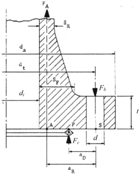
Figure description:
The provided image is a cross-sectional diagram of a fixed circular flange with a weldneck, showing various dimensions and force vectors.
Key Entities and Labels:
- Forces:
- : Upward external load vector acting along the axis of the pipe/neck.
- : Downward force vector acting through the bolt hole center (point S.
- : Upward reaction force vector acting at a contact point (point P.
- Dimensions:
- : Outer diameter of the flange.
- : Pitch circle diameter of the fasteners.
- : Inner diameter of the flange/pipe.
- : Diameter of the bolt hole.
- : Thickness of the pipe wall at the top.
- : Thickness of the neck section.
- : Thickness of the flange plate.
- : Radial distance from the contact point (P to the bolt hole center (S.
- : Radial distance from the internal wall axis (A to the bolt hole center (S.
- Reference Points:
- A: Point on the internal wall surface at the base.
- P: Point of contact/support on the flange face.
- S: Center point of the fastener/bolt hole.
- Structural Features:
- Cross-hatched area representing the flange and weldneck body.
- Centerline (dashed vertical line on the left indicating axis of symmetry.
Figure 8-15 - Dimensions of a Fixed Circular Flange (with a Weldneck)
In general, the contacting interstice between the fixed flanges can be either a large area or a small area. Only the case of the small contact area is considered in this theory.
8.3.2.4 Compliance of Loose Circular Flanges
Figure 8-16 shows the bending dimensions and bending deformations of a loose circular flange. For this flange the joint axis (O-O) and the external load axis (A-A) are generally coincident and as a result δ 3 is zero. Thus, the bending deformation due to an external load FA is only due to the increase in fastener load ∆ b a and is given by,
This is rearranged to give the flange compliance,
where ψ is the inversion compliance (defined in Section 8.3.2.5 below).
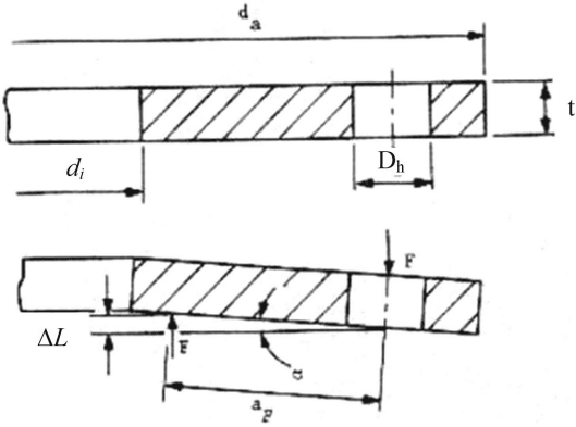
Figure description:
The image illustrates the bending deformation of a circular loose flange through two cross-sectional diagrams: one in an initial state and one in a deformed state.
Key Entities and Dimensions:
- : Outer diameter of the flange.
- : Inner diameter of the flange.
- : Thickness of the flange.
- : Diameter of the fastener hole.
- : Applied forces causing bending.
- : Vertical displacement/deformation at the inner edge.
- : Angle of rotation/deformation.
- : Radial distance between the applied opposing forces .
8.3.2.5 Inversion Compliance
The inversion compliance, , is given by,
where is a factor accounting for the presence of the holes in the flange given by,
or \frac{1}{12}(d_{i} + S_{F})S_{F}^{2} + \frac{1}{12}(d_{a} - d_{i} - d^{*})h^{2} \quad \text{(for fixed flanges)} \tag{8.3.13}
where and are flange annulus' outer and inner diameters (see Figure 8-15 and Figure 8-16), is the radial thickness of the weldneck (see Figure 8-15), is the thickness of the flange, and is defined by,
where is the diameter of the fastener holes, and is the flange nominal width specified in mm.
8.3.3 Force Ratio for Circular Cantilever Flanges
8.3.3.1 Single Flange
Consider a weld neck flange such as the one illustrated in Figure 8-15, fastened to an infinitely stiff surface such that only the flange undergoes bending deflections. During preloading the fastener extends by and the flange deflects by,
When the external load is added the fastener is stretched by,
The force ratio for the cantilevered flange joint, , can be defined as follows,
Using Equations [8.3.1], [8.3.2], [8.3.3] and [8.3.5],
Therefore, combining Equations [8.3.17] and [8.3.18] the force ratio expressed as a function of the compliances is,
For loose flanges where the clamping load and applied load are coincident and Equation [8.3.19] is simplified to,
8.3.3.2 Twin Flanges
The compliances derived in sections 8.3.2.2, 8.3.2.3, 8.3.2.4 and 8.3.2.5 are for individual cantilevered flanges. In many cases, the joint has two symmetric cantilevered flanges. For such a joint, with fixed flanges and bolts the force ratio is given by,
where and include the effects of both flanges and the increased (unlike those values used in the above sections 8.3.2.2 to 8.3.2.5).
For loose flanges, , and Equation [8.3.21] becomes simplified to,
where and are redefined to account for both flanges, as in equation[8.3.21].
8.3.4 Simplified Joint Diagram for Eccentric Joints
8.3.4.1 Overview
Consider a weld neck type flange, as shown in Figure 8-15 with m bolts. If the fasteners are equally preloaded by FV /m and consequently stretched by ( δ b ) m , the two flanges can bend by 2δ 1 F V while also being compressed by ( δ c ) m . This preloading is represented in the joint diagram of Figure 8-17 by the triangle SPV.
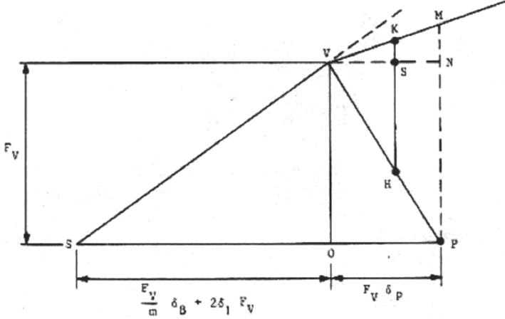
Figure description:
- Title: Figure 8-17 - Simplified Joint Diagram for Cantilevered Flanged Joints
- Axes/Dimensions:
- Vertical axis labeled
- Horizontal base dimension (left of O:
- Horizontal base dimension (right of O:
- Key Entities/Points:
- S: Origin/starting point of the left triangle base.
- P: Endpoint of the right triangle base.
- V: Peak point of the joint diagram, forming triangle SPV.
- O: Point on the base directly below V.
- M, N, K, S, H: Points located on or near the extension lines to the right of peak V.
- Graphic Elements:
- Solid lines forming a main triangle (SPV with a vertical divider (VO.
- An ascending solid line extending from V through K and M.
- A descending solid line from V through H to P.
- Dashed lines indicating projections for points M, N, and S.
Figure 8-17 - Simplified Joint Diagram for Cantilevered Flanged Joints
8.3.4.2 Onset of Separation
Separation occurs when the preload reduces to zero, which is represented by the line PM in Figure 8-17. At the onset of separation FA = PM (where MN is equal to ∆ A and NP is equal to ∆ A ). Thus,
[8.3.23]
8.3.5 Joint Diagram for Eccentric Nonlinear Joints
In the case of symmetrically flanged joint with a gasket or seal which has non-linear deformation characteristics, the clamped parts compliance δ is dependent upon the load. c
Assuming m fasteners, Equation [8.3.23] can be rearranged to give;
Since and are nonlinear, the joint diagram is also linear. To construct the joint diagram, a range of values of are assumed and using the gasket characteristics, the corresponding values of can be determined. Hence, the values of can be calculated and used to construct the joint diagram.
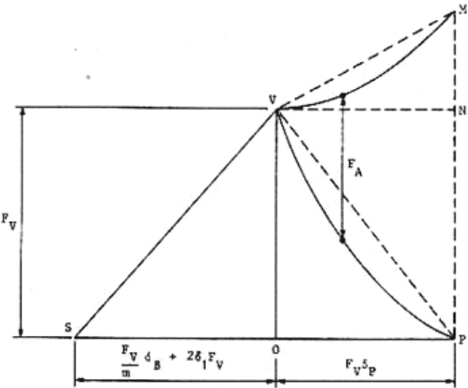
Figure description:
Technical Diagram with Geometric Labels
Geometric and Algebraic Parameter Relationship Diagram
Annotations
- F_V (dimension_line - position: Vertical distance from horizontal baseline to point V)
- F_A (dimension_line - position: Vertical distance between the upper and lower curves starting at V)
- S, O, P, V, N, M (text_label - position: Key vertices of the geometric construction)
- Dashed lines (reference_line - position: Represent linear theoretical relationships or coordinate projections)
| Element | Type | X-Coordinate / Range | Y-Coordinate / Range | Label |
|---|---|---|---|---|
| Point S | Point | -((F_V / m * δ_B + 2 * δ_1 * F_V)) | 0 | S |
| Point O | Point | 0 | 0 | O |
| Point P | Point | F_V * s_P | 0 | P |
| Point V | Point | 0 | F_V | V |
| Point N | Point | F_V * s_P | F_V | N |
| Point M | Point | F_V * s_P | y_M (where y_M > F_V) | M |
| Line SV | Straight Line | From S to V | [0, F_V | - |
| Curve VM | Curve (Convex) | [0, F_V * s_P | [F_V, y_M | - |
| Curve VP | Curve (Concave) | [0, F_V * s_P | [F_V, 0 | - |
| Dashed Line VM | Straight Line | [0, F_V * s_P | [F_V, y_M | - |
| Dashed Line VP | Straight Line | [0, F_V * s_P | [F_V, 0 | - |
| Dashed Line VN | Straight Line | [0, F_V * s_P | F_V | - |
| Dashed Line MP | Straight Line | F_V * s_P | [0, y_M | - |
| Dimension F_V | Vertical | Left of S | [0, F_V | F_V |
| Dimension F_A | Vertical | ~0.6 * F_V * s_P | Between Curves VM and VP | F_A |
| Dimension SO | Horizontal | [-d_SO, 0 | Below baseline | (F_V / m * δ_B + 2 * δ_1 * F_V) |
| Dimension OP | Horizontal | [0, F_V * s_P | Below baseline | F_V * s_P |
Notes: The chart is a technical geometric diagram representing physical parameters. Horizontal distances are defined as expressions involving F_V, m, δ_B, δ_1, and s_P. Curves indicate non-linear variations relative to the dashed linear approximations.
Figure 8-18 - The Joint Diagram for Non-Linear Gasket Joints