8.2.1 Compliance of the Clamped Parts
8.2.1.1 Overview
The equations for calculating the compliance of the clamped parts in the concentric loading case were given in Section 7.6. The eccentric case is more complicated since, in addition to longitudinal deformation, the eccentricity of the external load produces bending deformations in the flanges leading to additional extension of the joint. Hence, the longitudinal compliance of the flanges in an eccentric joint is greater than that of a concentrically loaded joint. Also, for joints with large areas of contact, the distribution of the clamping pressure depends on the magnitude of the external load (as discussed in Section 8.1), producing further changes in compliance.
A relatively simple analysis (modified from Reference 8.4) of eccentric joint deformation is possible if the following assumptions are made:
- • The clamped parts form a prismatic bending solid
- • There is no one-sided gapping (i.e. the interface pressure is always positive)
- • All the cross-sections of this prismatic solid remain flat under loading
- • A linear stress distribution is established in these cross-sections
- • The bending resistance of the fastener is much lower than that of the bending solid and can be neglected
These simplifying assumptions limit the joints that can be considered to those in which the interface area loaded by one fastener, Aj , is not much greater (3 to 5 times) the underhead area. Serious errors can occur if larger areas are assumed (see Reference 8.2). Additionally, it is important that the joint’s transverse width, C, and clamping eccentricity, s, satisfy the following relations:
where C is the distance from the fastener joints axis to the flange edge as indicated in Figure 8-7. It is important that joints that do not satisfy these criteria are analysed using FEM or testing.
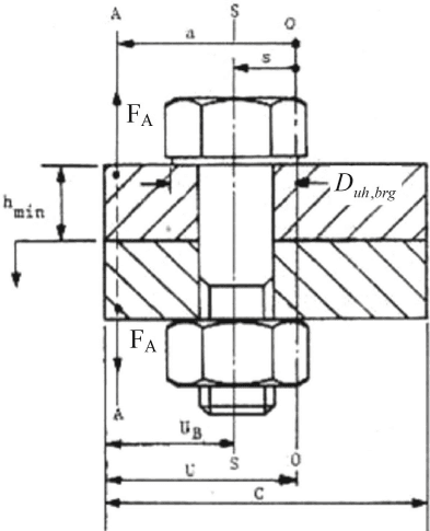
Figure description:
- Entities: Bolt with a hexagonal head and nut, two clamped plates (cross-hatched, and force vectors.
- Forces: (applied tensile forces acting along axis A-A.
- Dimensions/Variables:
- : Distance from axis O to axis A.
- : Distance from axis O to bolt centerline S.
- : Thickness of the top plate.
- : Bearing diameter under the bolt head.
- : Distance from left edge to bolt centerline S.
- : Distance from left edge to axis O.
- : Total width of the clamped interface.
- Reference Axes:
- A: Axis of applied force.
- S: Centerline of the bolt.
- O: A reference axis located to the right of the bolt centerline.
In a multi-fastener joint such as Figure 8-8 the spacing between fasteners (fastener pitch) is defined as , and the flange length assumed to be loaded by each fastener is defined as , which is assumed to be given by,
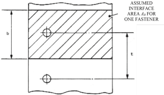
Figure description:
Entities and Dimensions:
- Assumed Interface Area for One Fastener: Indicated by the cross-hatched rectangular region.
- : The width/length of the shaded interface area.
- : The distance (pitch between the centerlines of two adjacent fasteners/holes.
- Fasteners/Holes: Represented by two circular features with horizontal centerlines.
The clamped interface area shown in Figure 8-8 has an area, , and a radius of gyration,
where is the second moment of area of the clamped interface (about its neutral axis), which is given by for the interface shown in Figure 8-8.
Subject to the above assumptions, clamped parts compliance values can be calculated for the two classes of eccentric joints shown in the following sections.
8.2.1.2 Eccentric Joints Loaded at the Fastener Axis
This class of joints has the external load is introduced at the fastener axis (i.e. ), as shown in Figure 8-9.
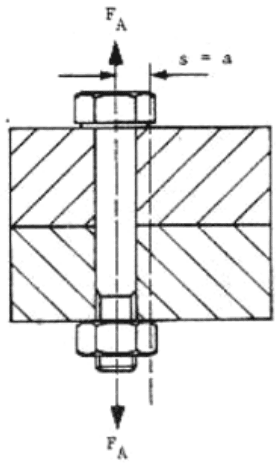
Figure description:
Key Entities:
- Bolt: Fastener with a hexagonal head.
- Nut: Fastener component at the bottom of the assembly.
- Clamped Parts: Two cross-hatched blocks joined by the bolt.
Visible Details:
- : Axial force vectors pointing away from the top and bottom of the fastener.
- : Labeled horizontal distance between the center axis of the bolt and a parallel dashed vertical line.
- Dashed Lines: Indicate the central axis of loading and a secondary vertical reference line.
- Interface: A horizontal line dividing the two clamped blocks.
The compliance of the clamped parts, , is higher than and is calculated by multiplying the compliance of an equivalent concentric joint by an eccentricity factor, according to,
which can be written in a more simple form as,
where is the length ratio given by,
where is the effective clamping area defined below in Section 8.2.1.4.
8.2.1.3 General Case of an Eccentric Joint
This (more general) class of joints is shown in Figure <mark>7.2.4</mark>, and has clamped parts compliance given by,
where; is defined by equation [8.2.7].
The value of in equation [8.2.8] is always taken as positive. The value of is positive if S-S and A-A are on the same side of O-O or negative if they are on opposite sides. Thus, can be either greater than or less than .
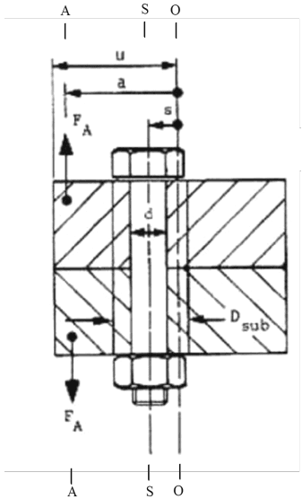
Figure description:
- Entities: Bolted joint assembly featuring a bolt with a hexagonal head and nut, two clamped plates, and a designated compression zone indicated by hatching.
- Reference Lines:
- Line A-A: Axis for external force application.
- Line S-S: Central axis of the bolt.
- Line O-O: Fulcrum or pivot axis.
- Dimensional Parameters:
- u: Distance from line A-A to line O-O.
- a: Distance from the force application point to line O-O.
- s: Distance between the bolt axis (S-S and the reference line O-O.
- d: Nominal diameter of the bolt shank.
- D_sub: Diameter or width associated with the effective clamping/compression zone.
- Forces:
- F_A: Opposing external tension forces applied along axis A-A.
8.2.1.4 The Effective Clamping Area
The effective clamping area, , used in equation [8.2.7] is the cross-sectional area of the assumed compression zone (see Section 7.6.2) at its greatest extent, and is calculated as follows,
- a. For a clamped sleeve with narrow flanges with ,
- b. For wide flanges with ;
- c. For the intermediate case with
8.2.2 The Joint Diagram
The joint diagram developed for concentric joints in Section 7 can also be used to describe the characteristics of eccentric axially loaded joints.
Triangle , , of Figure 8-11 represents the preloaded condition where the fastener tension is equal and opposite to the compressive load on the clamped parts . As the external eccentric load increases from zero the fastener extends under the partial load . This causes the clamped parts to lose compression linearly until the point when the joint begins to separate at the side nearest the load . During this phase the straight line to represents the behaviour of the clamped parts. If is further increased, the joint characteristics change to that of a hinge and lever producing a nonlinear load-deflection response of the clamped parts. The fastener therefore feels a high proportion of the external load than predicted by extrapolation of the line .
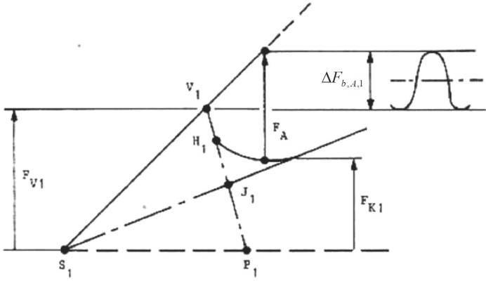
Figure description:
Schematic Diagram of Geometric Forces
Force and Geometric Relationships Diagram
Annotations
- F_V1 (vertical_line - position: left side, between baseline and v1 level)
- F_A (vertical_line - position: center, between top line and curve)
- F_K1 (vertical_line - position: right side, from baseline up)
- Delta F_b,A,1 (vertical_line - position: top right, height of pulse)
- Pulse waveform (text_label - position: upper right)
| Label | Description |
|---|---|
| S1 | Origin point on the horizontal dashed baseline |
| P1 | Secondary point on the horizontal dashed baseline to the right of S1 |
| v1 | Peak point at the intersection of a solid line from S1 and a horizontal line |
| H1 | Intermediate point on the dashed segment connecting v1 and P1 |
| J1 | Intersection point of the dashed line v1-P1 and a lower solid ray from S1 |
| F_V1 | Vertical distance from the baseline to the horizontal level of v1 |
| F_A | Vertical dimension between the upper slanted line and a curved segment |
| F_K1 | Vertical height measured from the baseline to the lower solid ray |
| Delta F_b,A,1 | Vertical magnitude of the pulse waveform shown on the right |
Notes: The diagram shows a geometric construction involving several points and vertical measurements labeled as forces or distances (F_V1, F_A, F_K1, Delta F_b,A,1. It includes a pulse waveform on the far right with its vertical extent marked relative to the horizontal level established at point v1.)
Figure 8-11 - The Joint Diagram for Eccentrically Loaded Joints showing the Non- Linearity of the Clamped Parts
Figure 8-12 shows the load increment in the fastener due to the same dynamic external load , and illustrates the fact that higher preload (indicated by ) delay the onset of separation and thus . The figure also indicates that, after one-sided opening commences, the higher the preload reduces the load increment in the fastener, i.e. .
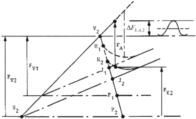
Figure description:
Technical Engineering Diagram Geometric construction showing force or displacement vectors
Technical Schematic Analysis
Legend
- Solid line — color: black; symbol: Solid line style
- Dashed line — color: black; symbol: Dashed line style
- Dash-dot line — color: black; symbol: Dash-dot line style
Annotations
- Delta F_b,A,2 (text_label - position: Top right sinusoidal fluctuation)
- FV2 (vertical_line - position: Leftmost vertical dimension line)
- FV1 (vertical_line - position: Center-left vertical dimension line)
- FA (vertical_line - position: Upper central vertical dimension line)
- FK2 (vertical_line - position: Rightmost vertical dimension line)
| Label | Element | Description |\n| :--- | :--- | :--- |\n| S2 | Point | Base point located at the bottom left of the diagram. |\n| V2 | Point | Intersection vertex at the top of the primary diagonal from S2. |\n| H1 | Point | Upper point on the dashed curved path following V2. |\n| H2 | Point | Lower point on the dashed path below H1. |\n| J1 | Point | Reference point on an intermediate dash-dot line. |\n| J2 | Point | Upper point on the secondary steep diagonal line. |\n| P1 | Point | Intermediate point on the secondary steep diagonal line, defining the base of FV1. |\n| P2 | Point | Bottom point of the secondary steep diagonal line segment. |\n| FV2 | Dimension | Total vertical height from the S2 reference level to the top horizontal line through V2. |\n| FV1 | Dimension | Vertical height from the horizontal level through P1 to the top horizontal line. |\n| FA | Dimension | Vertical distance between the extension of the diagonal line and the curved path. |\n| FK2 | Dimension | Vertical height from the bottom reference plane to the level of point J2. |\n| Delta F_b,A,2 | Dimension | Amplitude of the periodic sinusoidal variation shown at the top right. |
Notes: The diagram illustrates a series of geometric relationships between various points (S2, V2, H1, H2, J1, J2, P1, P2 and their associated vertical dimensions (F. A periodic signal variation is also characterized at the top right.))
Figure 8-12 - Joint Diagram with a Higher Preload
8.2.3 The Force Ratio
For an eccentric axially loaded joint with a large contact area, assuming the clamped parts behave linearly, it can be shown that the force ratio, Φ e, n , prior to one-sided opening is given by,
where and are defined in Section 8.2.1, and is defined below in Section 8.2.4.
As was the case for concentric joints, the force ratio is used to determine the incremental loads experienced by the fastener and clamped parts due to the externally applied force according to the relations; and .
The difference in the force ratio compared with that of the equivalent concentric joint is the quantitative consequence of the “prying” effect (see Section 8.1.2).
8.2.4 Loading Plane Factor
For eccentric axially loaded joints, the loading factor derived in Section 7.7 need to be corrected. The assumption is made that all cross-sections stay planar during deformations of the joint. First the loading plane factor has to be determined for a theoretical joint, where the fastener’s longitudinal axis is moved to a point that leads to a concentric axially loaded joint. Then the eccentric loading plane factor is calculated with,
where; is the concentric loading plane factor from Section 7.7.
8.2.5 The Interface Opening Limit
Figure 8-13 shows the limiting value of the external load, , at which the interface begins to open. This is calculated by,
where is the eccentricity f the point of first gapping (relative to the joint axis O-O).
Conversely for a given external load, , there can be a value of preload, , at which one-sided opening can just occur,
where is the clamping force at the onset of interface gapping as given by,
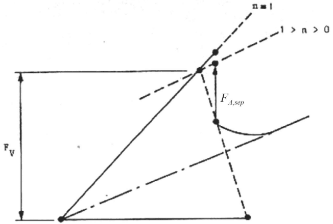
Figure description:
Geometric Analysis of Force Components
Force and Slope Geometric Diagram
Annotations
- F_V (vertical_dimension - position: Left-hand side, vertical height indicator)
- F_{A,sep} (vertical_vector - position: Middle-right, vertical distance between the n=1 line and the curved boundary)
- n = 1 (line_label - position: Associated with the top-most dashed diagonal line)
- 1 > n > 0 (line_label - position: Associated with the second dashed diagonal line from the top)
| Feature | Label | Description |
|---|---|---|
| Origin Point | - | Intersection point of the baseline and multiple sloped lines at the bottom left |
| Steep Sloped Line | n = 1 | Dashed line extending from the origin to the top right |
| Shallow Sloped Line | 1 > n > 0 | Dashed line extending from the origin to the right with a lower slope than n=1 |
| Dash-Dot Line | - | Line extending from the origin between the horizontal baseline and the 1 > n > 0 line |
| Baseline | - | Solid horizontal line extending from the origin to the right |
| Vertical Dimension | F_V | Double-headed vertical arrow indicating the height from the baseline to the top horizontal reference line |
| Separation Force | F_{A,sep} | Vertical arrow pointing upwards from a curved line to the n=1 line |
| Reference Points | - | Black dots marking specific locations: origin, baseline end, line intersections, and vector endpoints |
Notes: The diagram illustrates a relationship between various sloped parameters (n=1, 1 > n > 0 and force components (F_V, F_{A,sep}. It includes a mix of solid, dashed, and dash-dotted lines with specific intersection points highlighted by dots.))
See Reference 8.4 for the derivation of the equations [8.2.14] and [8.2.15].
Figure description:
Text: ECSS
Key Entities:
- Letter 'E'
- Letters 'CSS'
Visual Details:
- The letter 'E' is purple and italicized, set within a white parallelogram.
- The letters 'CSS' are white and italicized, set within a purple parallelogram.
- The overall shape is a combined parallelogram with a purple border.
8.2.6 Preload Considerations
8.2.6.1 Preload Scatter
The effects of preload scatter due to friction variables during assembly are the same for eccentric joints as for concentric joints, and are described in Section 6.
8.2.6.2 Preload Loss
Embedding, as described in Section 6.4.2, mainly occurs after preloading but before external loading is applied. The amount of embedding preload loss for an eccentric joint can be calculated as for a concentric joint from,
where fZ is the plastic deformation caused by embedding as given by Table 6-3, and Φ e, n is the force ratio.