8.4.1 Bending Moments
8.4.1.1 Overview
The bending moment in an eccentric joint causes bending stress in the fastener. This stress needs to be considered in addition to the direct stresses caused by and and be taken into account, particularly when determining the fatigue endurance limit.
Considering the loads acting on the upper clamped part of Figure 8-19, the sum of moments about the joint axis O-O is,
The change in due to the externally applied load is given by the first two terms in the right hand side of Equation [8.2.17]. Thus, the increment to the moment can be written as,
According to Reference 8.3 this moment increment is partly absorbed by the clamped parts, as , and partly by the fastener as (as is the case for axial loads), according to the ratio of the bending compliances. This leads to the relation,
which can be simplified for to give,
[8.4.4]
where is the bending compliance of the clamped parts given by,
and is the bending compliance of the fastener given by,
where is the length of the 'th segment of the fastener, and is the second moment of area of the 'th segment of the fastener, and is the young's modulus of the fastener.
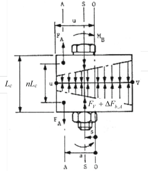
Figure description:
Entities:
- Fastener: A bolt and nut assembly securing two plates.
- Joint Interface: The horizontal line between the two clamped plates.
- Force : Applied external tensile force acting along axis A.
- Force : Internal clamping force acting along the bolt axis S.
- Moment : Applied bending moment.
- Pressure Distribution: Linear, trapezoidal distribution across the interface from point to point .
Dimensions and Axes:
- Axis A: Loading axis.
- Axis S: Bolt centerline axis.
- Axis O: Right-side reference axis.
- : Total clamp length.
- : Effective clamp length.
- : Distance from axis A to axis O.
- : Distance from axis A to axis S.
- : Distance from axis S to axis O.
8.4.1.2 Fastener Stress under Combined Axial and Bending Loads
The determining factor for the endurance limit of the fastener in an eccentrically loaded joint is generally the nominal stress . This arises from the longitudinal force and the moment for the tension fibre subject to the greatest stress in the minor cross-section at the first load-bearing thread turn. This is calculated from,
Substituting for , and , [8.4.7] can be rewritten as,
where; the expression to the right of the brackets is the stress arising only from the force , and the expression in brackets is its relative increase as a result of the additional bending stress.