5.5.1 Overview
Table 5-4, extracted from ECSS-E-ST-32-10C Rev. 2 Corrigendum 1, shows the recommended safety factors for the analysis of threaded fasteners in European space projects (e.g. on behalf of ESA). Ultimate responsibility for the definition of safety factors for a space project rests with the project management. Since safety factors depend strongly on the type of load, the stated safety factors are to be regarded as minimum values.
The safety factors can be decreased significantly if a test with the appropriate test factor is performed either on dedicated test structure identical to the flight structure (a proto-type test) or on the flight hardware (a proto-flight test).
| Structure type | Vehicle | Requirements | |||
|---|---|---|---|---|---|
| FOSY | FOSU | FOSY verification by analysis only | FOSU verification by analysis only | ||
| Joints and inserts: a - Failure - Gapping/Sliding (Safety Critical) d - Gapping/Sliding (other) | Satellite | 1,1 | 1,25 | 1,25 | 2,0 |
| N/A | N/A | ||||
| 1,1 | 2,0 | ||||
| Launch vehicle e | 1,1 | 1,25 | N/A | N/A | |
| N/A | 2,0 | ||||
| 1,1 | 2,0 | ||||
| Man-rated S/C | See Note c | 1,4 | See Note c | See Note c | |
| 1,4 | 2,0 | ||||
| 1,25 | 2,0 | ||||
| Elastomer system and elastomer to structure connectionb | Satellite | See Note c | 2,0 | See Note c | See Note c |
| Launch vehicle | See Note c | 2,0 | See Note c | See Note c | |
- a These factors are not applied on the bolts preload
- b Analysis and test are performed to show that the possible non linear dynamic behaviour of the elastomer does not jeopardize the satellite strength and alignment.
- c No commonly agreed value within the space community can be provided.
- d For Safety Critical Structures definition applicable to man rated s/c see NASA SSP 52005
- e See requirement 4.3.2.2b of ECSS-E-ST-32-10C Rev.2 Corrigendum 1: " For expendable launch vehicles, FOSU and FOSY to failure, gapping and sliding, associated with thermally induced loads shall be 1,0."
5.5.2 The Joint Fitting Factor
In cases where the joint load distribution is difficult to accurately predict, it is important to apply an extra joint fitting factor of 1,15 in addition to the safety factors provided in Table 5-4. This factor is used on yield and ultimate loads in the structural analysis of all fittings with threaded fasteners, whose strength is not proven by limit and ultimate load test in which the actual stress conditions are simulated and measured in the joint and surrounding structure. It is important to apply this factor to all portions of the fitting, the means of fastening, and the bearing on the members joined.
The fitting factor is not used with limit and ultimate loads where the specific type of joint is strength- verified by comprehensive limit and ultimate tests. This commonly is the case for joints such as continuous row of fasteners in sheet or plate.
5.5.3 Planarity of Flanges
The absence of planarity between flanges can generate bending on the screw (see Figure 5-8).
In most cases this angle is so small with regard to the stiffness of the screw that the induced constraint is negligible, but in some specific designs (e.g. long screws) this has to be considered with different possible solutions:
- • Spherical washers to suppress this imposed angle
- • Or decrease of the torque/tension to maintain an acceptable safety margin on the screw.
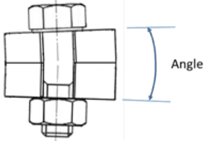
Figure description:
- Entities: Hexagonal bolt head, screw/bolt shank, washer, two non-parallel (tapered flange blocks, and a hexagonal nut.
- Key Detail: A blue double-headed arrow labeled "Angle" indicates the angular misalignment between the top and bottom surfaces of the joined flanges.
- Observation: The lack of planarity in the flanges causes the bolt head and nut to sit at an angle relative to the bolt's vertical axis.
Figure 5-8 - Illustration of bending on the screw